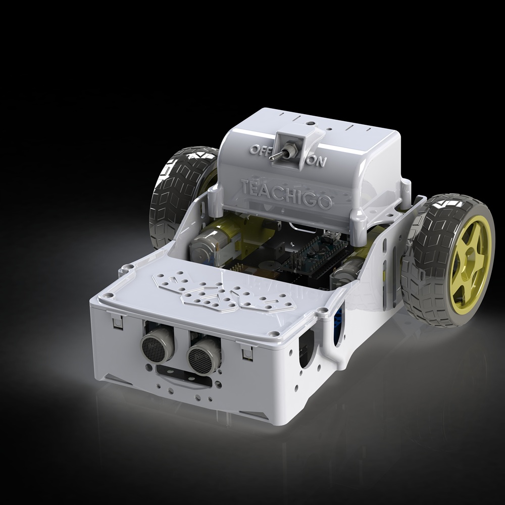
In this lesson we will learn how to use the knowledge we have from analog write lesson to actually build a robot that moves around, It will b driven by two motors , that`s why we call it Two Wheel Drive or 2WD. For Steering we will use Differential Steering.
Estimated time: 15 minutes
You will learn about:
Digital Write
Motor Function
Direction control
Speed Control
2WD
Differential Steering
Components Needed
Main Board | USB Cable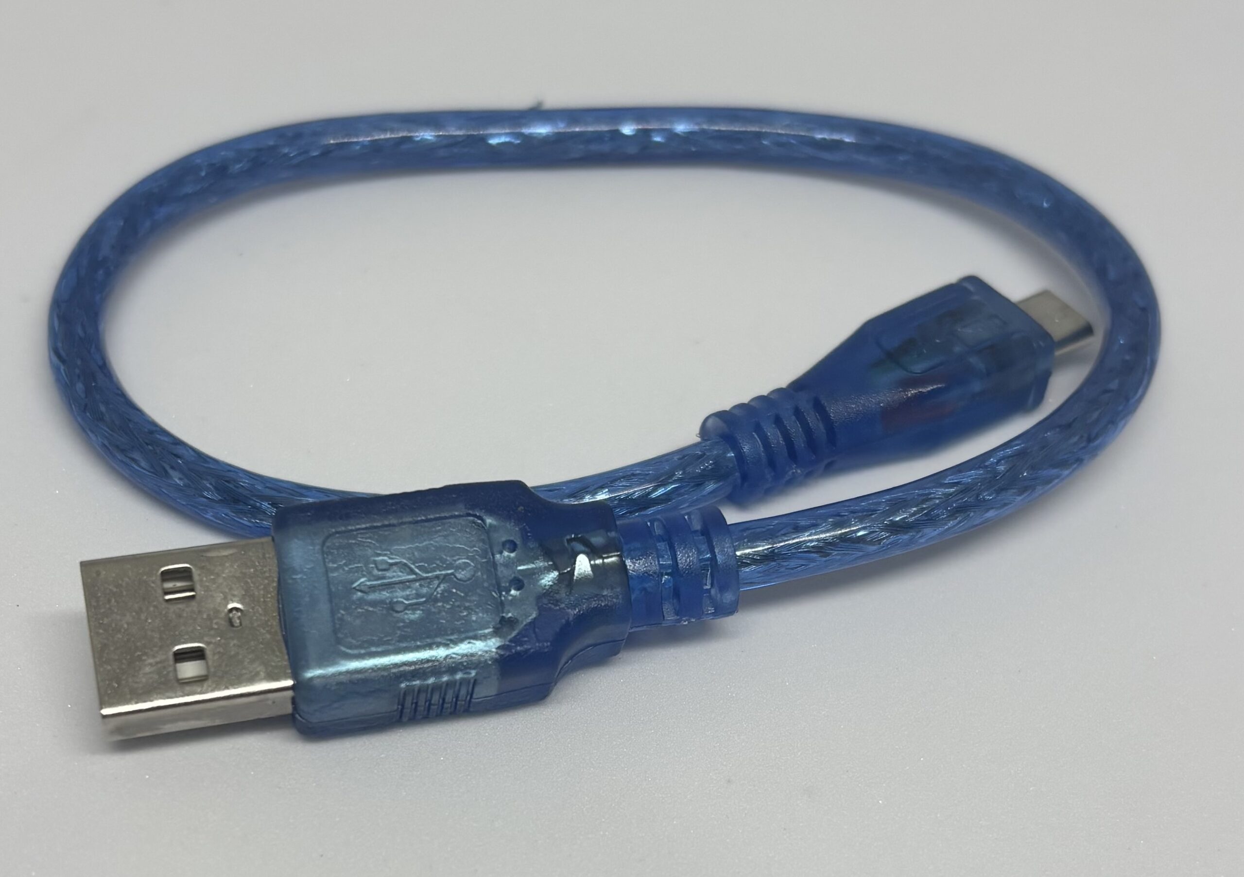 |
Arduino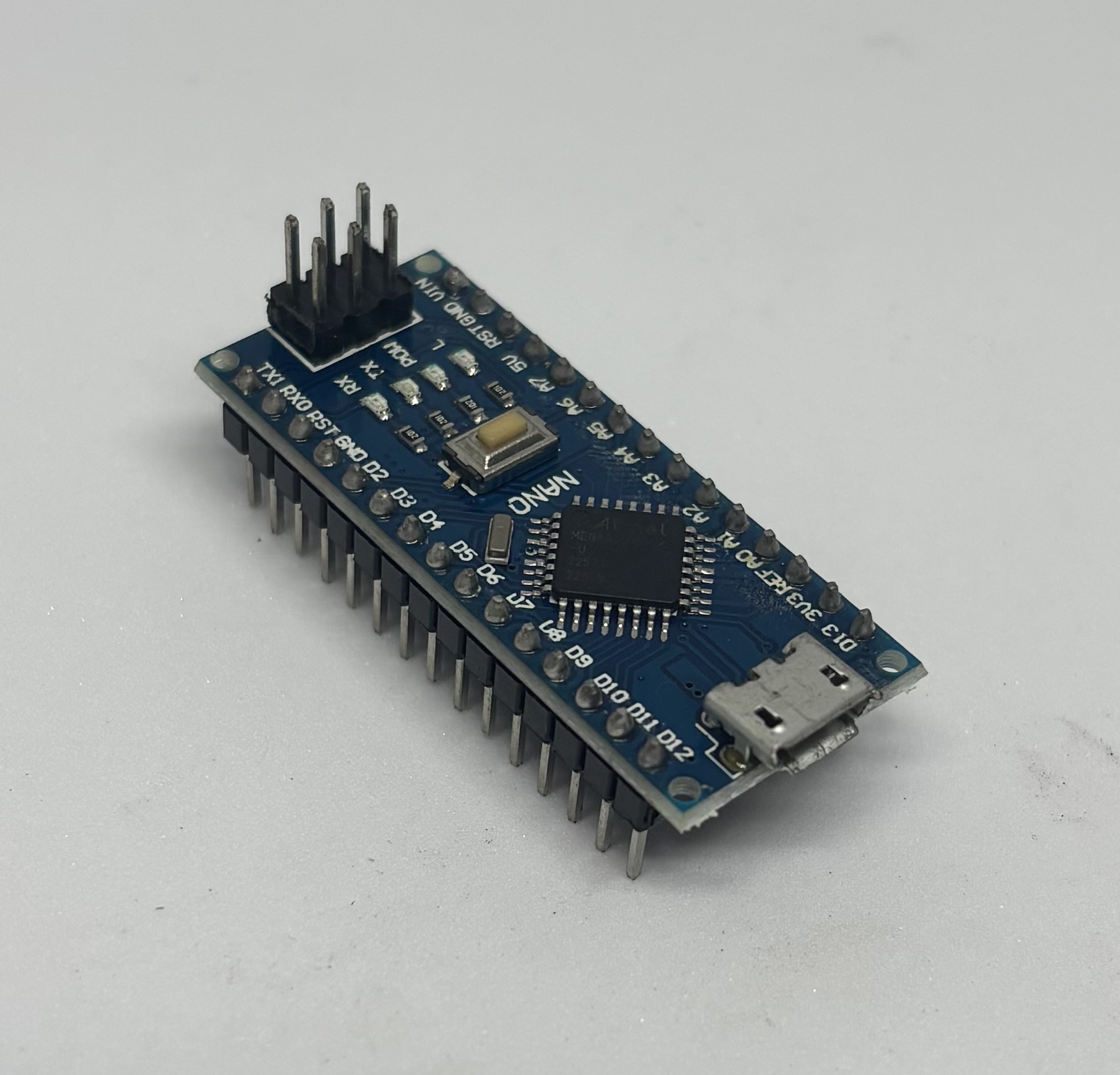 | Body |
2 pieces Motors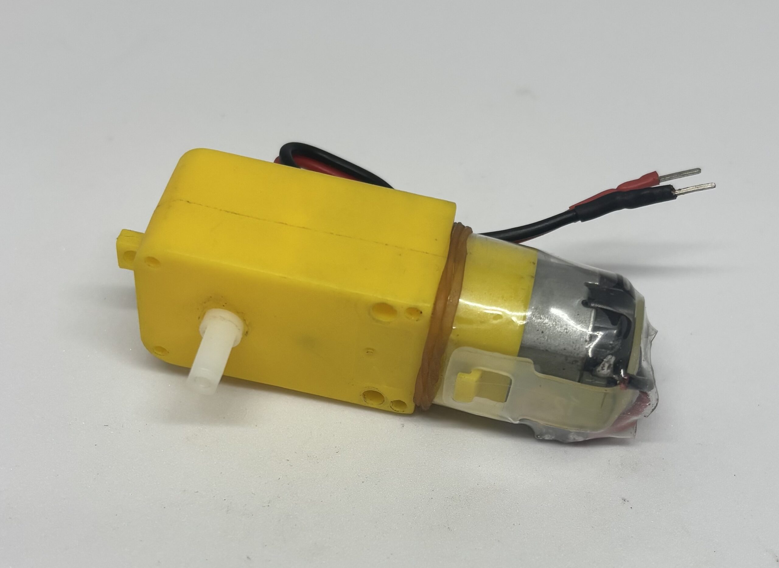 | 2 pieces Wheels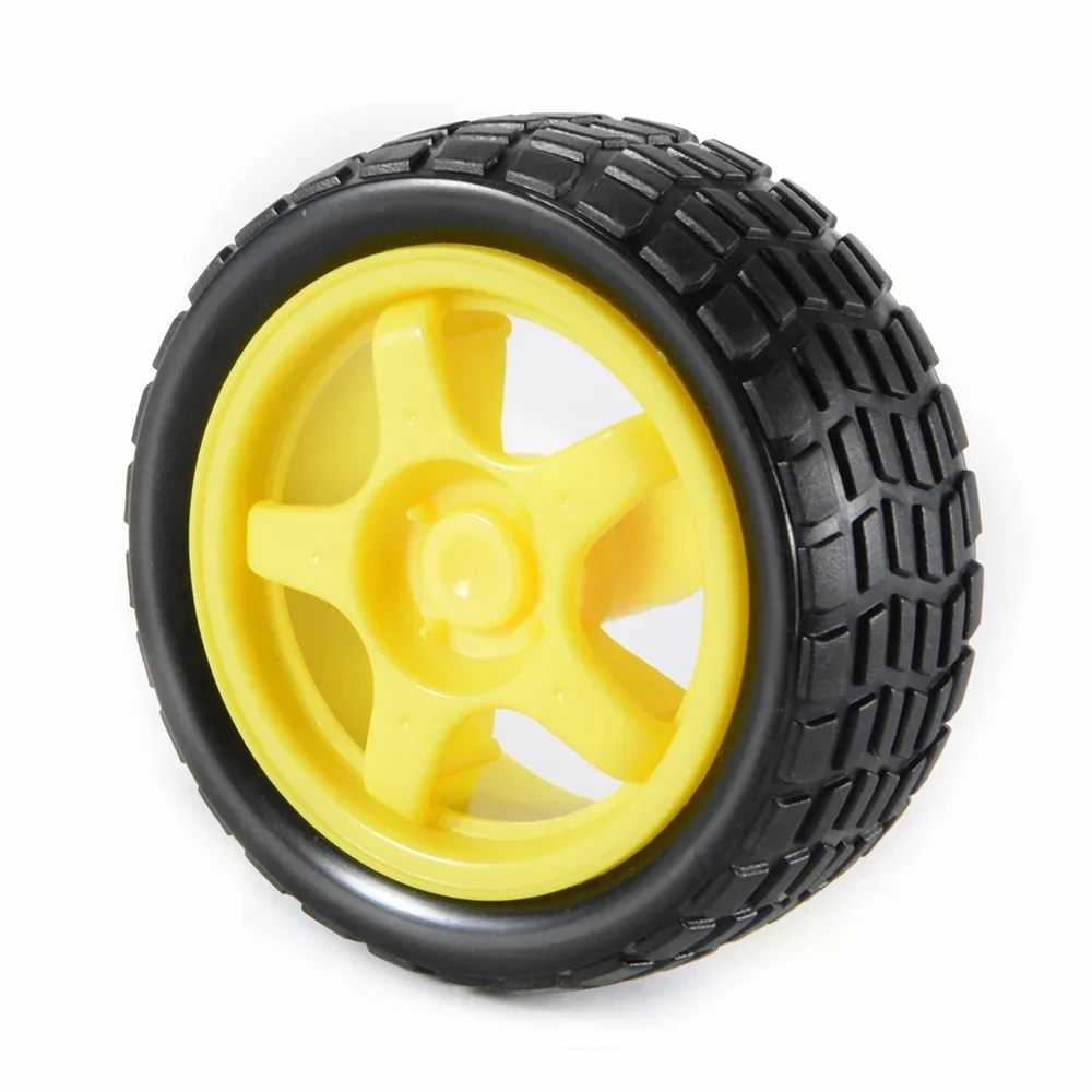 |
Hood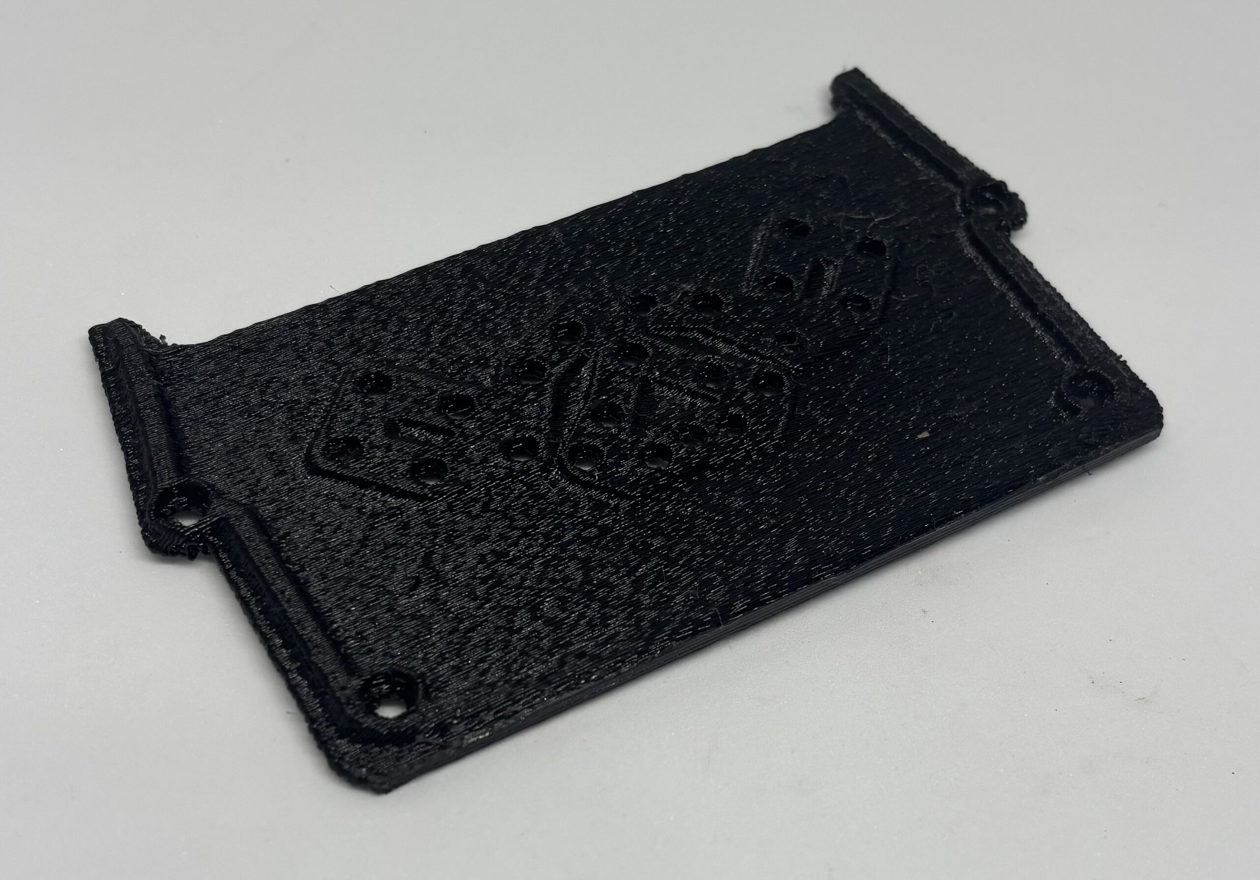 | 2 pieces Spacers |
17 pieces/ M3 Flat Washer | 4 pieces M3 nylon washers |
10 pieces M3 x 8 Screws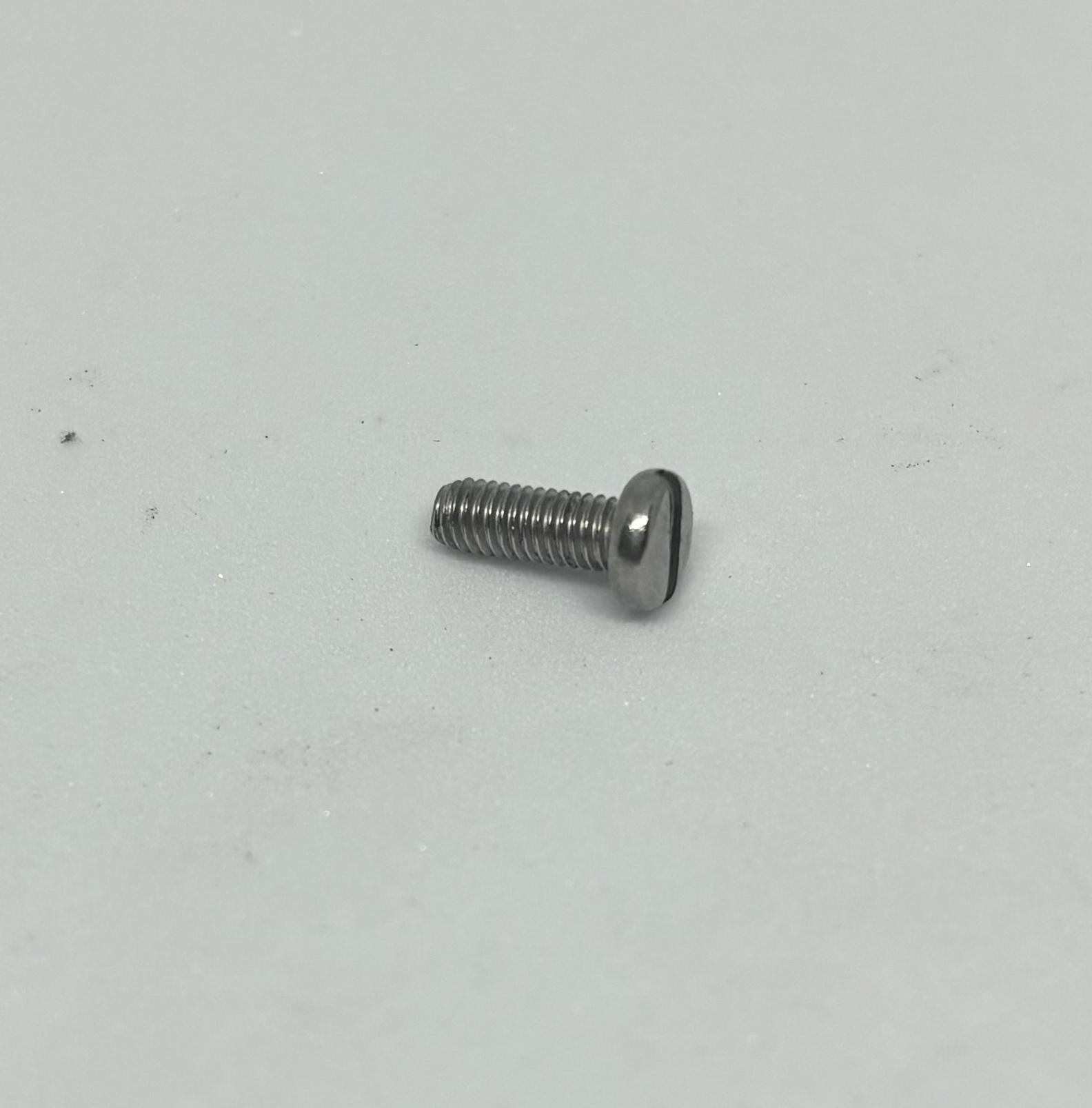 | 2 pieces M4 x 45 screws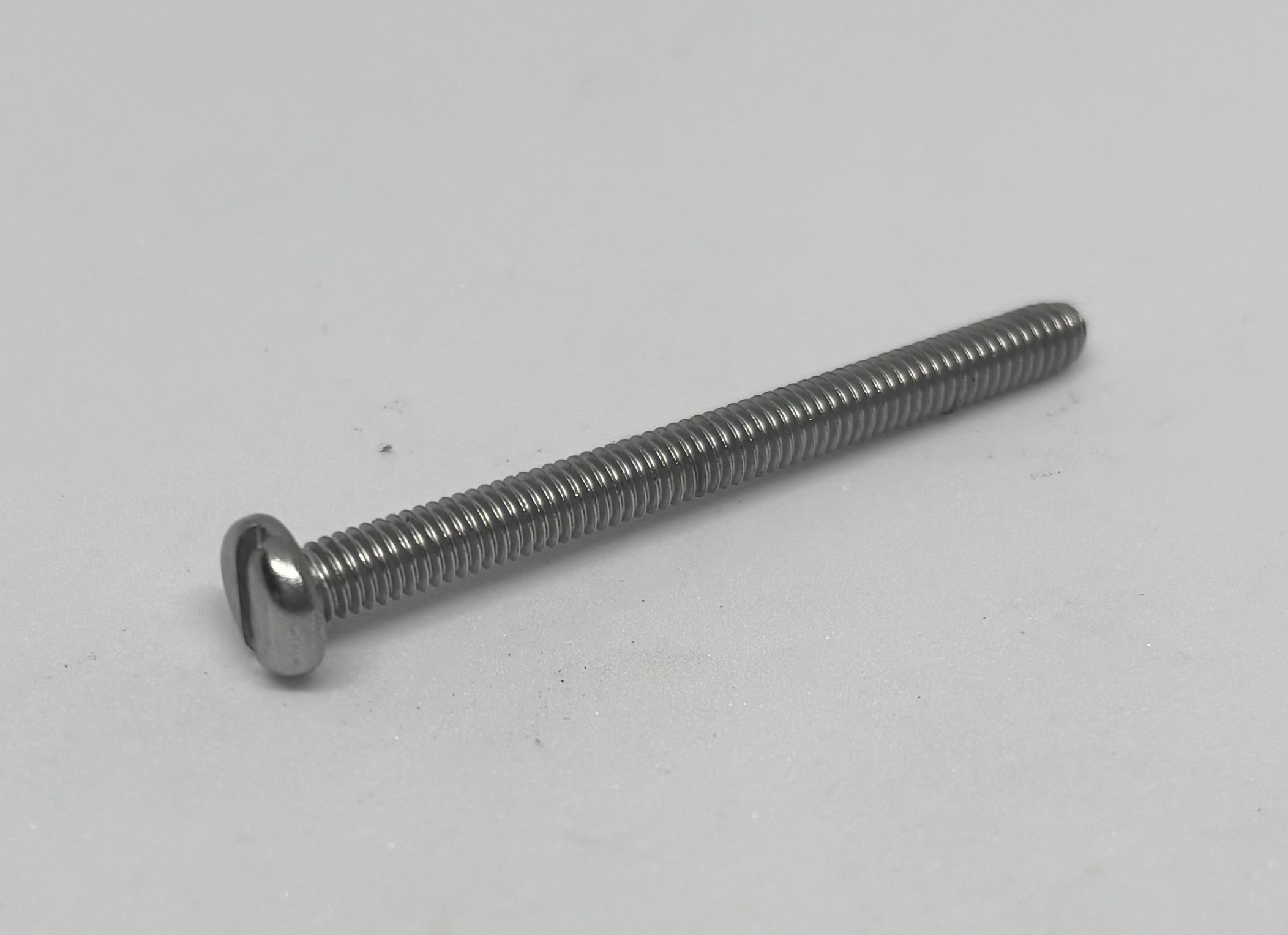 |
8 pieces M4 hex nuts | 4 pieces M4 nylon Washers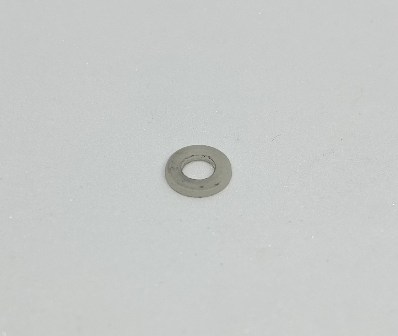 |
2 pieces M4 Lock Washers | 4 pieces M4 Flat Washers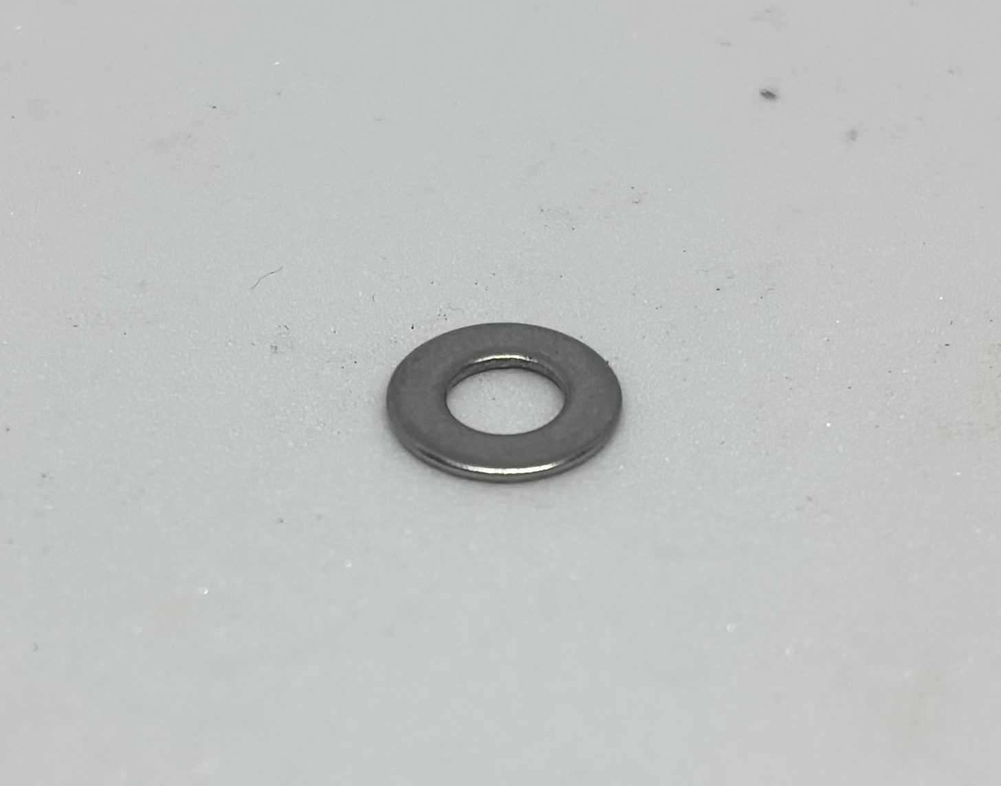 |
Caster Wheel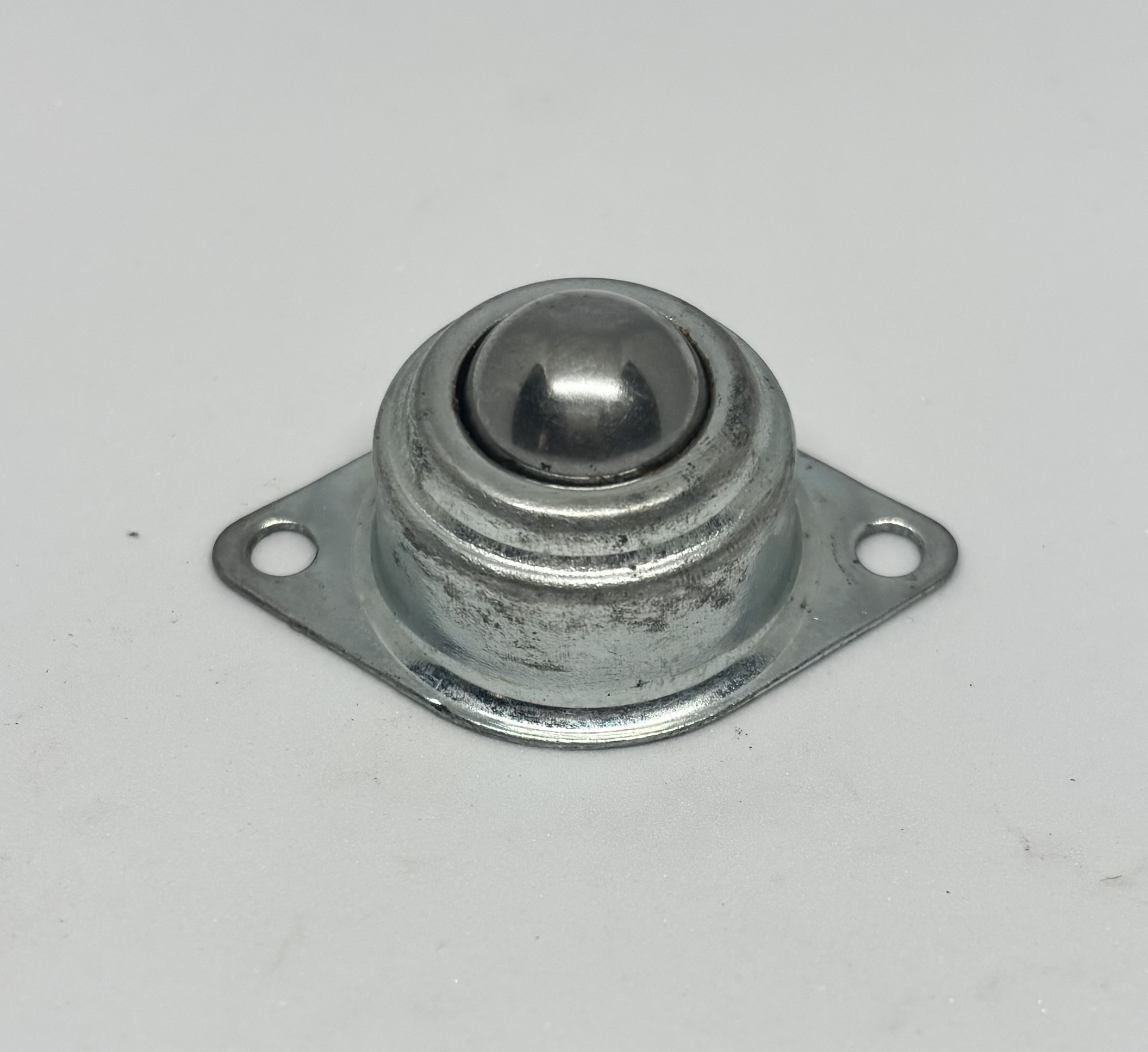 | Screw Driver |
Pliers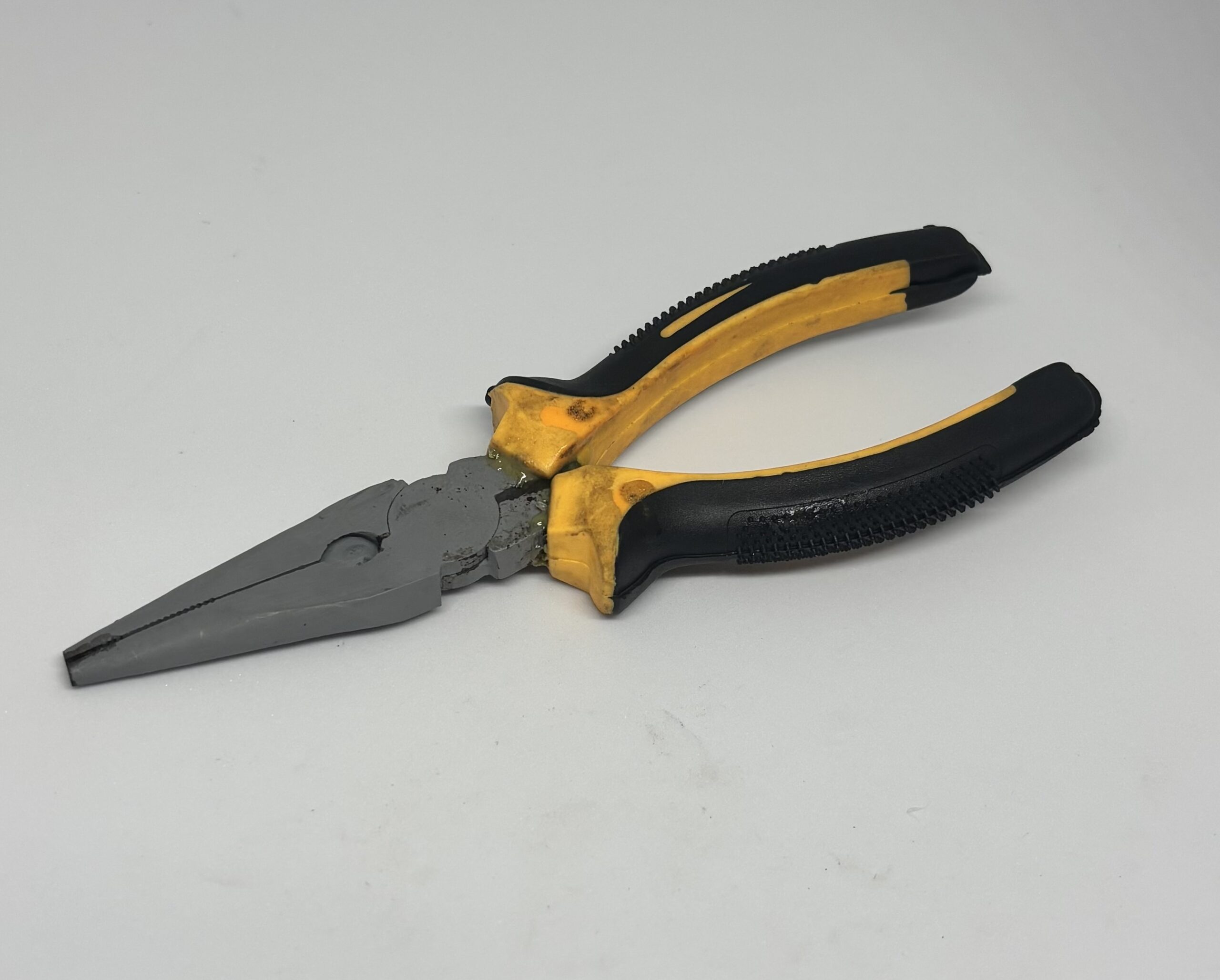 | 6 pieces/ M3 x 30 Screws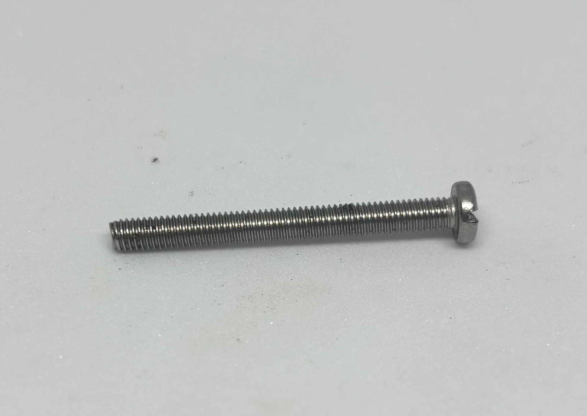 |
10 pieces/ M3 Hex Nut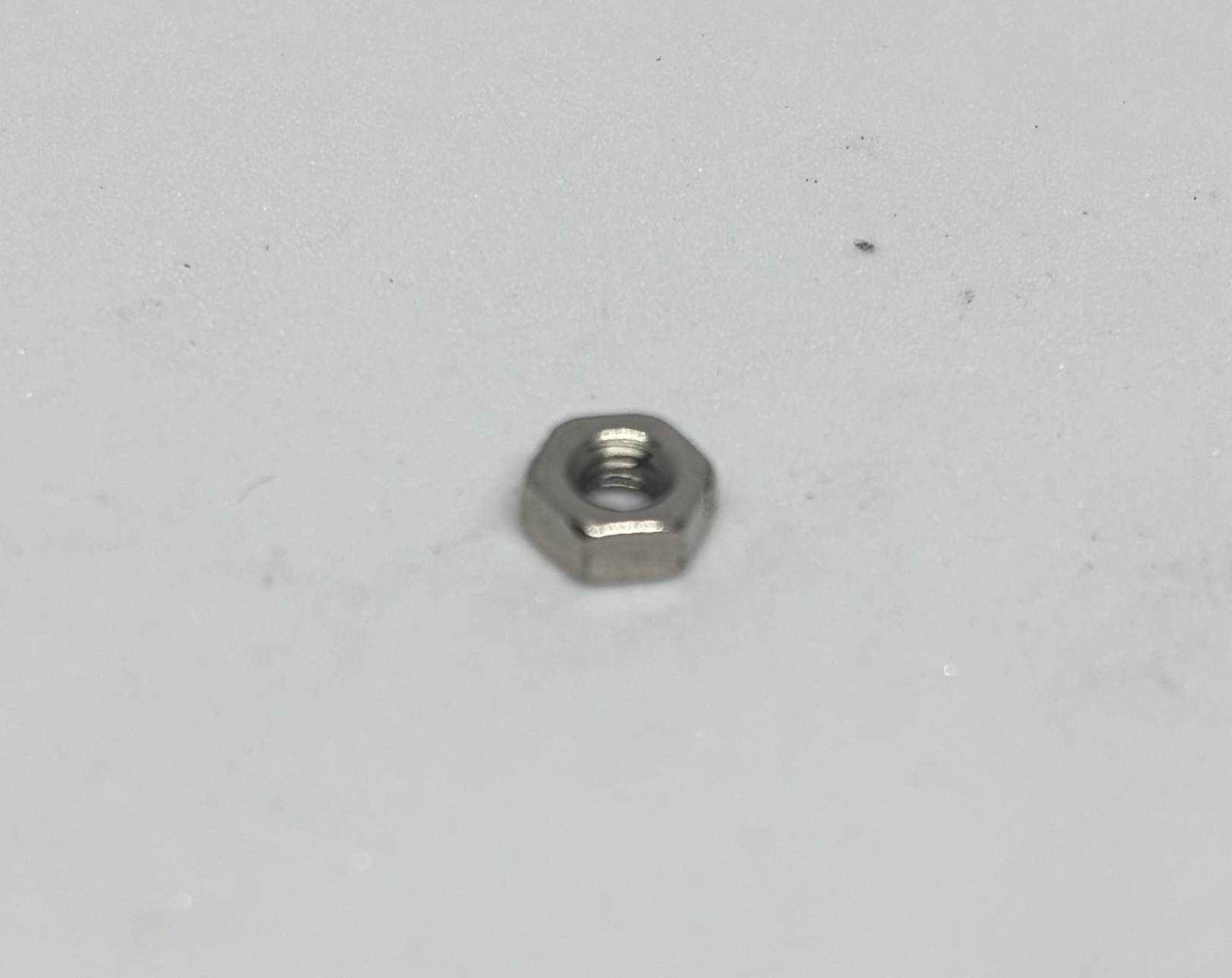 | 12 pieces/ M3 Lock Washer |
Step 1:
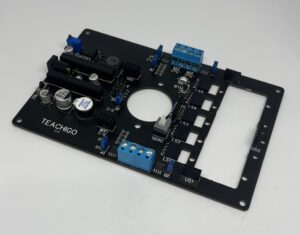
Install Mainboard on the body [|] using screw driver and pliers.
Step 2:
Install the Caster Wheel on the Main Board using M4 Screws .
Step 3:
Install the motors on the both sides of the body [|] using 6 M3 x 30 screws, 12 flat washers , 6 lock washers and 6 hex nuts.
Step 4:
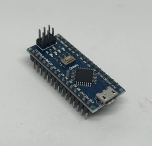
Connect [|] the Arduino to the Main board.
Step 5:
Plug in the USB cable[|] to the Micro USB port of Arduino and then plug it to the USB port of the computer.
Step 6:
Upload [|] the following code to the Arduino.
int M1A=3;
int M1B=4;
int M2A=2;
int M2B=5;


void setup() {

pinMode(M1A, OUTPUT);
pinMode(M1B, OUTPUT);
pinMode(M2A, OUTPUT);
pinMode(M2B, OUTPUT);
}

void loop() {

// Forward
  //M1 Forward
digitalWrite(M1B,LOW);
digitalWrite(M1A,HIGH);
  //M2 Forward
digitalWrite(M2B,LOW);
digitalWrite(M2A,HIGH);

delay(2000);

// Backward
  //M1 Backward
digitalWrite(M1B,HIGH);
digitalWrite(M1A,LOW);
  //M2 Backward
digitalWrite(M2B,HIGH);
digitalWrite(M2A,LOW);

delay(2000);

//Right
  //M1 Backward
digitalWrite(M1B,HIGH);
digitalWrite(M1A,LOW);
//M2 Forward
digitalWrite(M2B,LOW);
digitalWrite(M2A,HIGH);

 delay(2000);

//Left
  //M1 Forward
digitalWrite(M1B,LOW);
digitalWrite(M1A,HIGH);
//M2 Backward
digitalWrite(M2B,HIGH);
digitalWrite(M2A,LOW);

 delay(2000);

//Stop
  //M1 Stop
digitalWrite(M1B,LOW);
digitalWrite(M1A,LOW);
//M2 stop
digitalWrite(M2B,LOW);
digitalWrite(M2A,LOW);

 delay(2000);

}
Step 7:
Remove the USB cable from the USB port of Arduino.
Step 8:
Connect the motor wires to M1 and M2 Screw terminal using the screw driver. The red wire goes to The Terminals closer to Cellpack, the black wires goes to the terminals away from Cellpack.
Step 9:
Install the spacers by removing the two screws at the hood part of the robot and placing the spacers on top and fastening the screws from beneath having the Nylon washers touching the Mainboard and flat washer and spring washers under it .
Step 10:
Install the Hood on the body with M3 x 10 screws.
Step 11:
Install the Cellpack in its place [|] and connect the DC power jack Connector to female DC connector on the Mainboard.
Step 12:
Put the 2C , 3C , 4C and 5C Jumper Caps [|] in the connecting state so the two corresponding pins connect to each other.
Step 13:
Turn the Cellpack on [|] and check the movement of the robot, we have four movements, robot forward, robot backwards,robot turning right, robot turning left.
Congratulations! You have your own Robot now.
Code Explanation
- In lines 1 ,2 ,3 and 4 [|]
- In lines 7 to 13 ,[|] .
- In lines 9 to 12,[|] .
- In lines 17 to 23,[|] .
- In lines 19 and 20,[|] .
- In lines 22 and 23,[|] .
- In line 25,[|] .
- In lines 29 to 33,[|] .
- In line 35,[|] .
- In lines 37,to 43, [|]
- In lines 47 to 53,[|] .
- In lines 57 to 63,[|] .
Further Experimentation
- Try using analog write instead of digital write for 3 and 5 pins and try giving the robot different speeds.
- Try using other turning strategies like one motor pause, the other one going forward or other one going backwards.
- Try increasing the delay times and see for the going forward part the robot exactly goes on a straight line, if not , try calibrating the motors by giving different speeds to motors.
Practical Usage For our Projects
- We will use these codes for all kinds of robots on wheels and will combine that with other configurations to build remote controlled robots and transformer robots.