In this lesson we will learn how to use the analog write function to turn on our motors and set their speed. We can use analog write function for our PWM[|]
[Pulse Width Modulation, or PWM, is a technique for getting analog results with digital means. Digital control is used to create a square wave, a signal switched between on and off. This on-off pattern can simulate voltages in between the full Vcc of the board by changing the portion of the time the signal spends on versus the time that the signal spends off. Only some of the pins of our Arduino have this ability, they are: 3, 5, 6, 9, 10, 11]
pins.
Estimated time: 7 minutes
You will learn about:
Analog Write
Motor Function
Direction control
Speed Control
If Statement
Components Needed
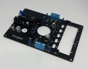
Main Board
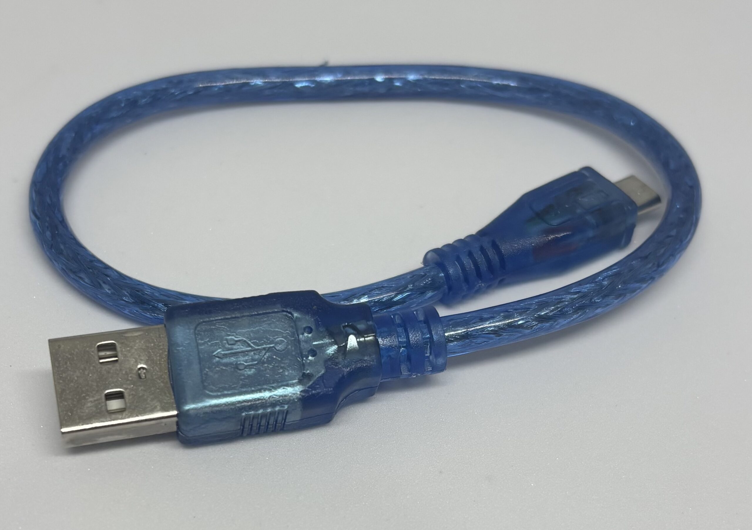
USB Cable
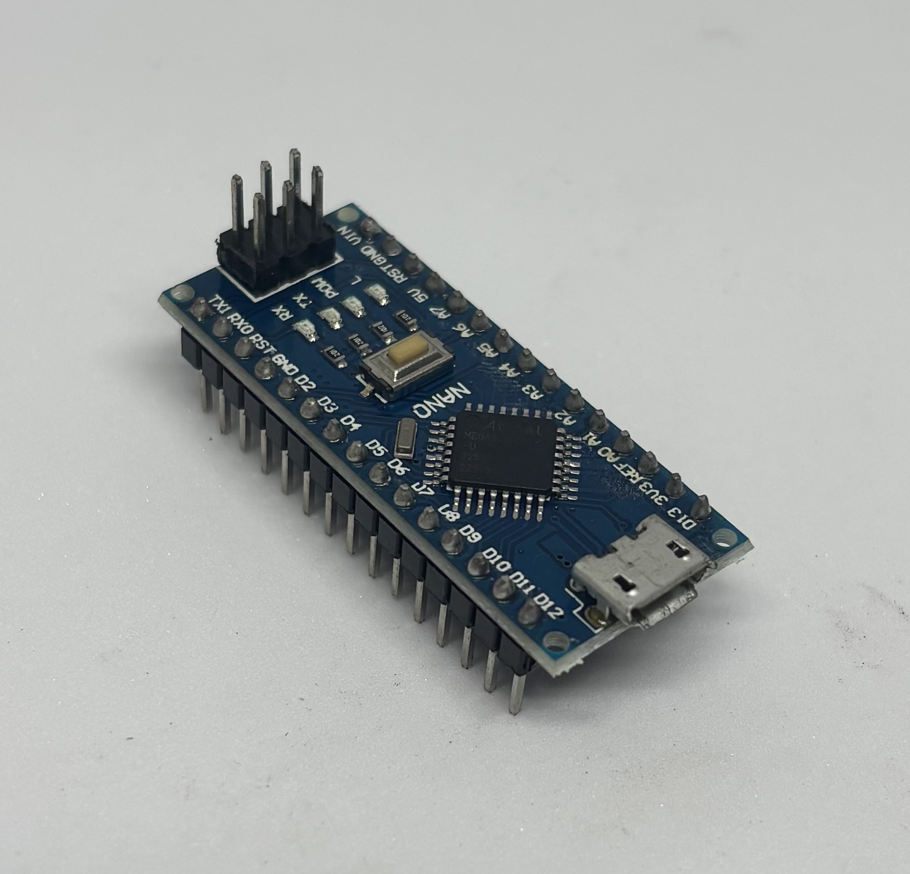
Arduino
Body
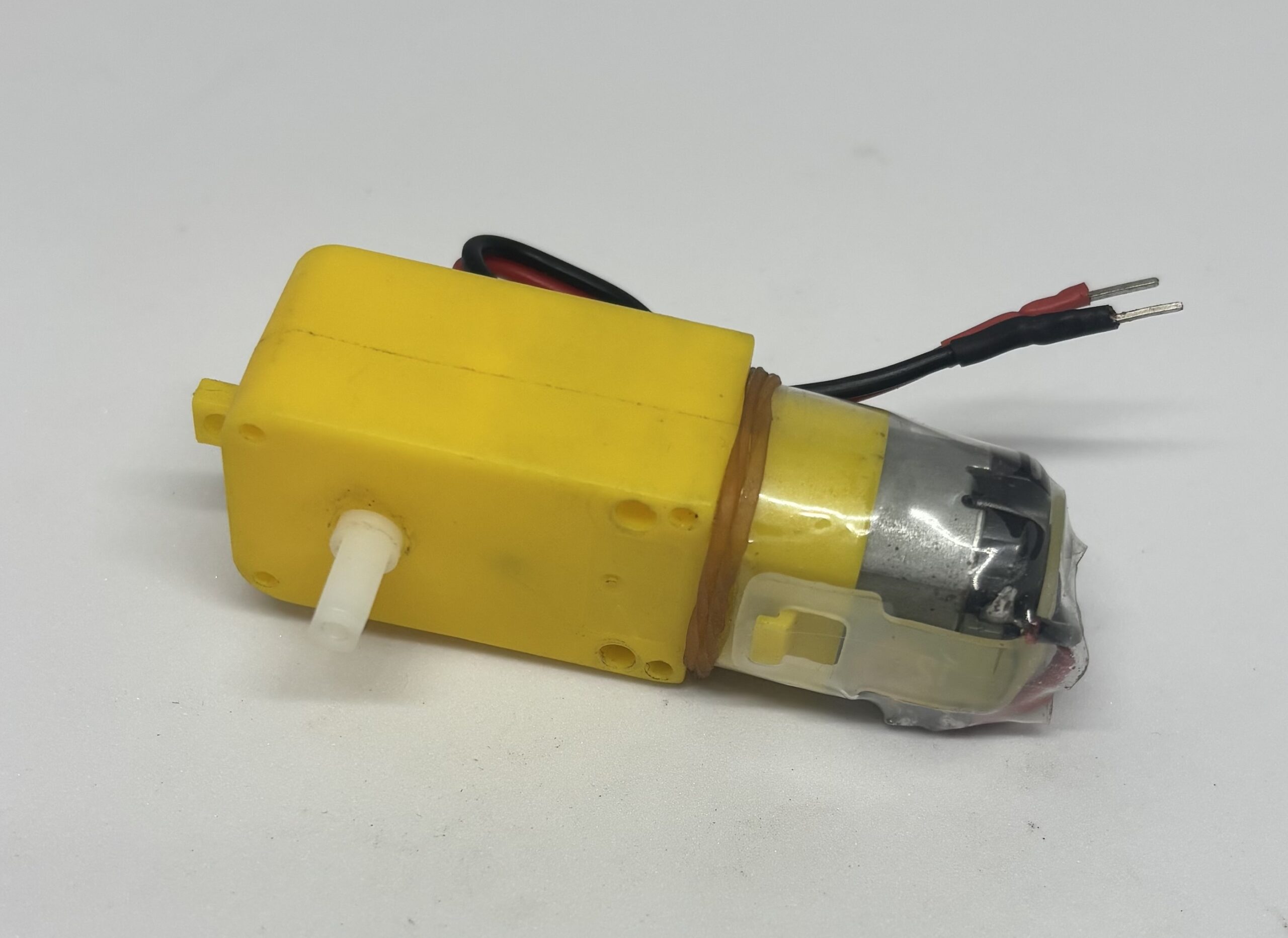
Motor
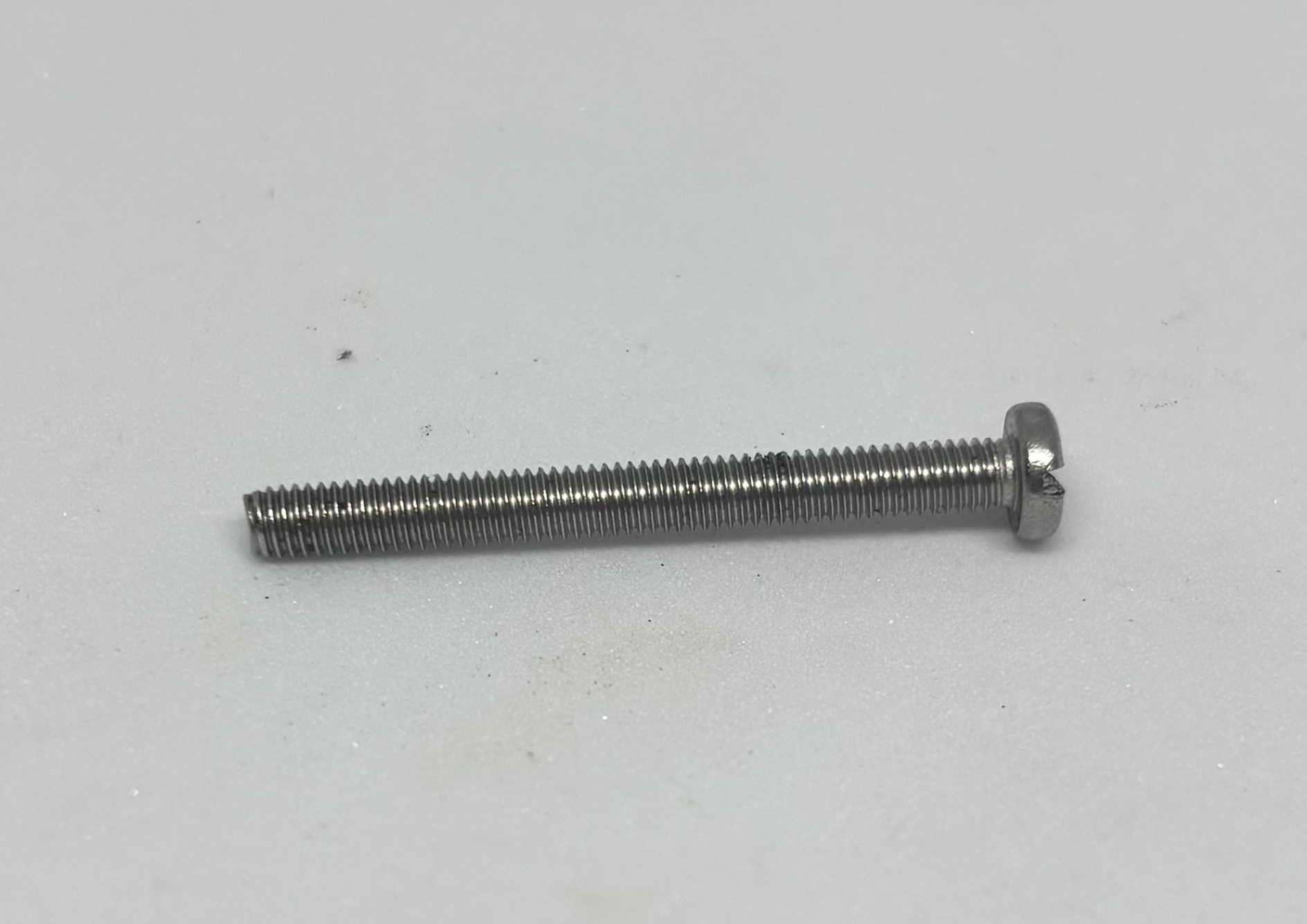
3 pieces/ M3 x 30 Screws
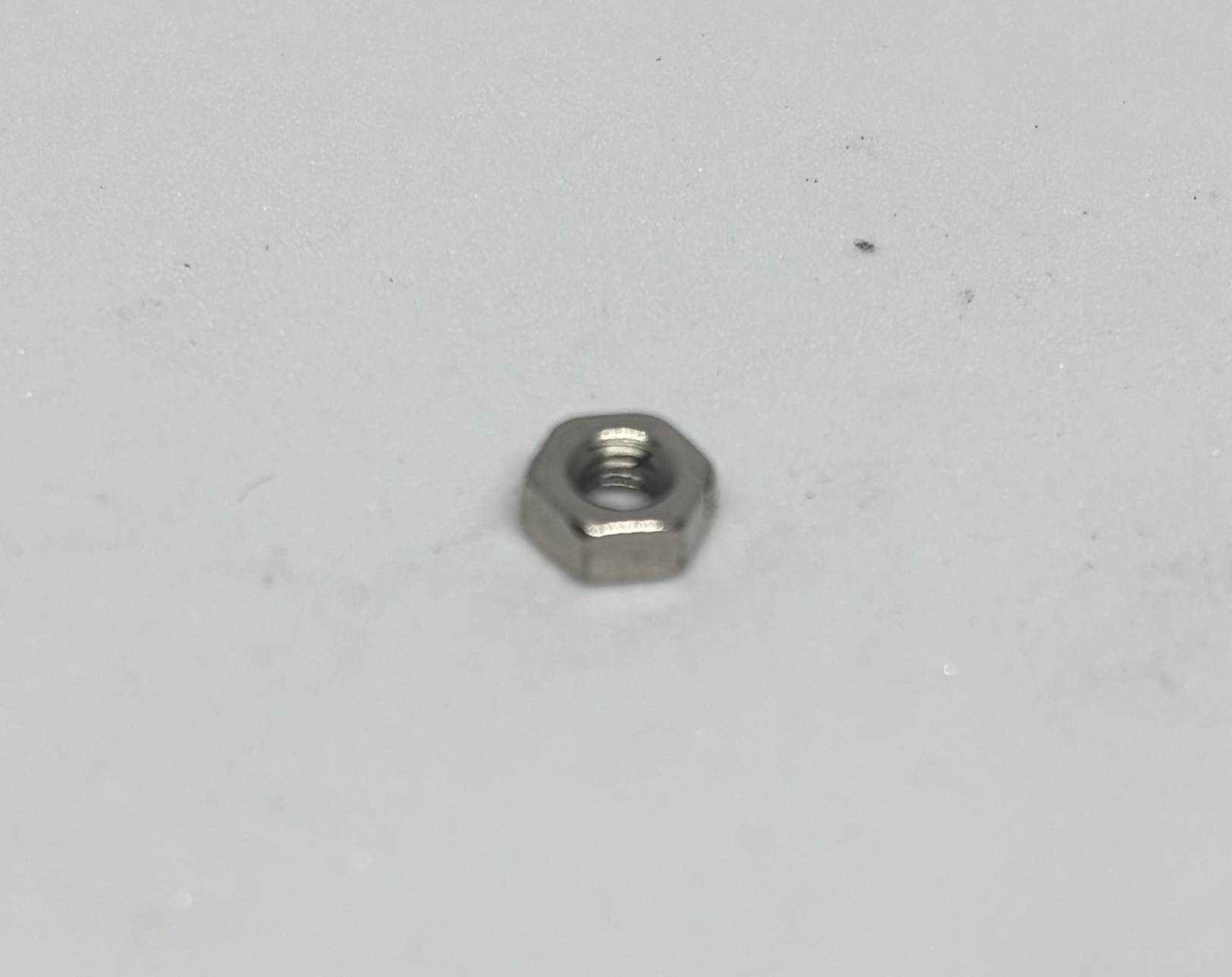
14 pieces/ M3 Hex Nut
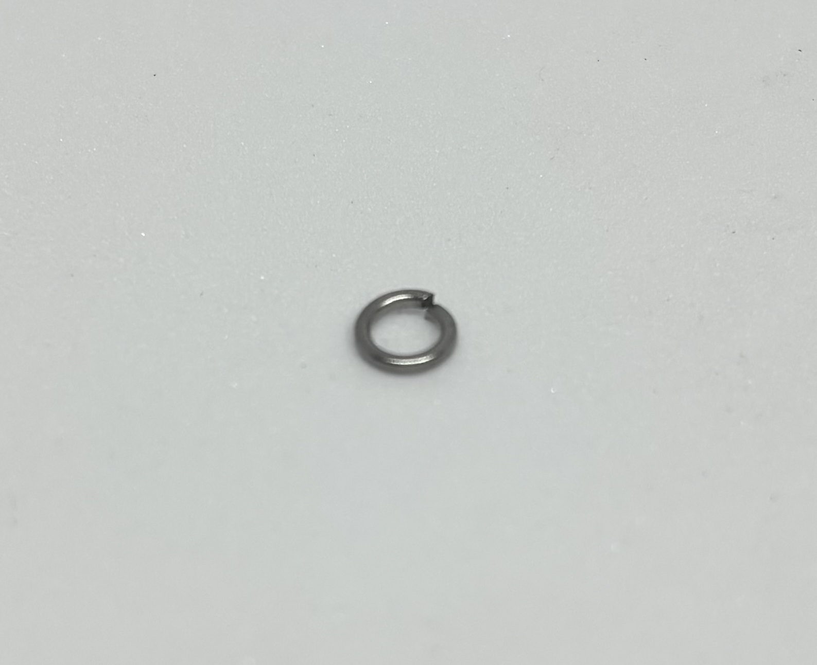
9 pieces/ M3 Lock Washer
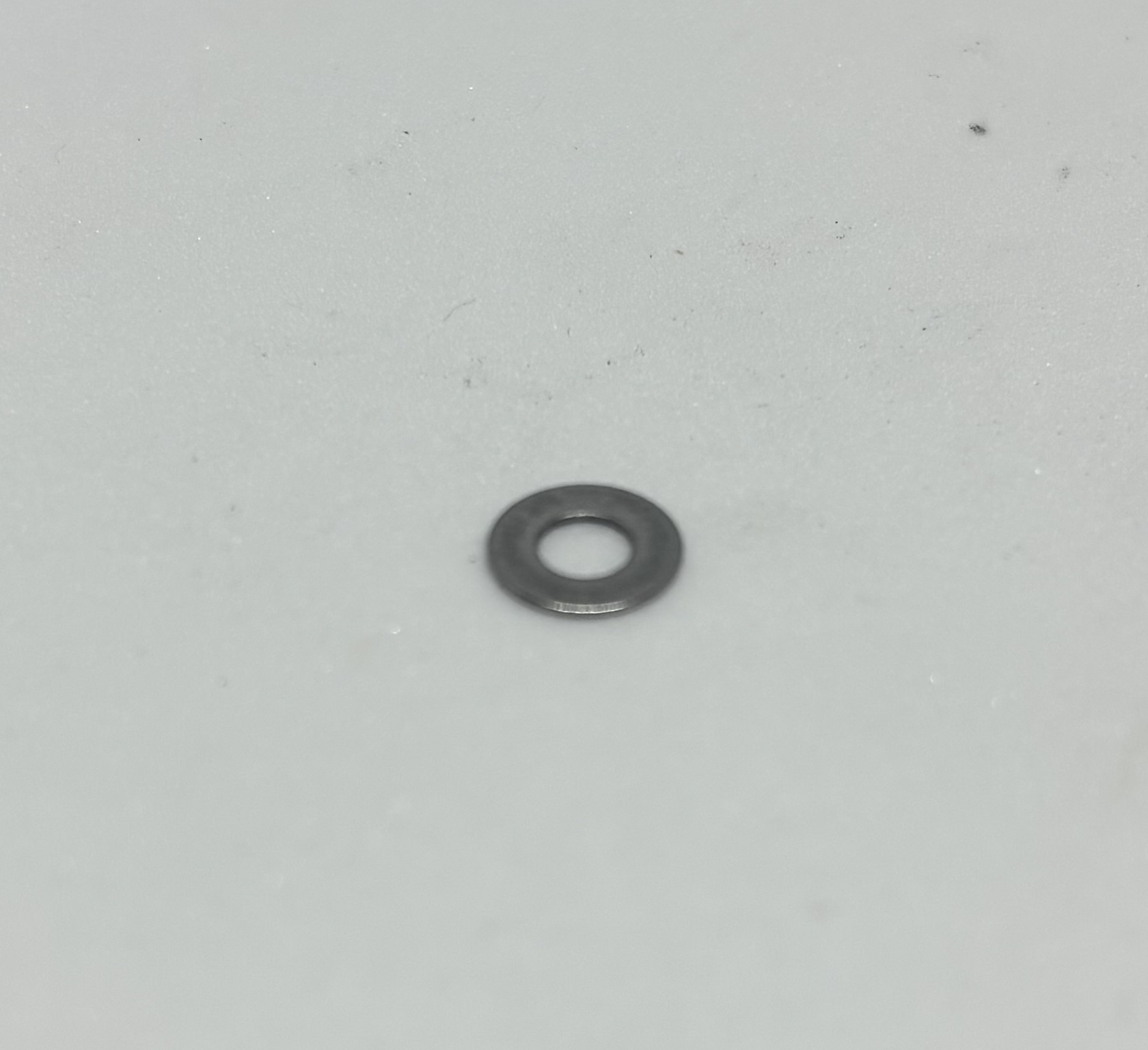
14 pieces/ M3 Flat Washer
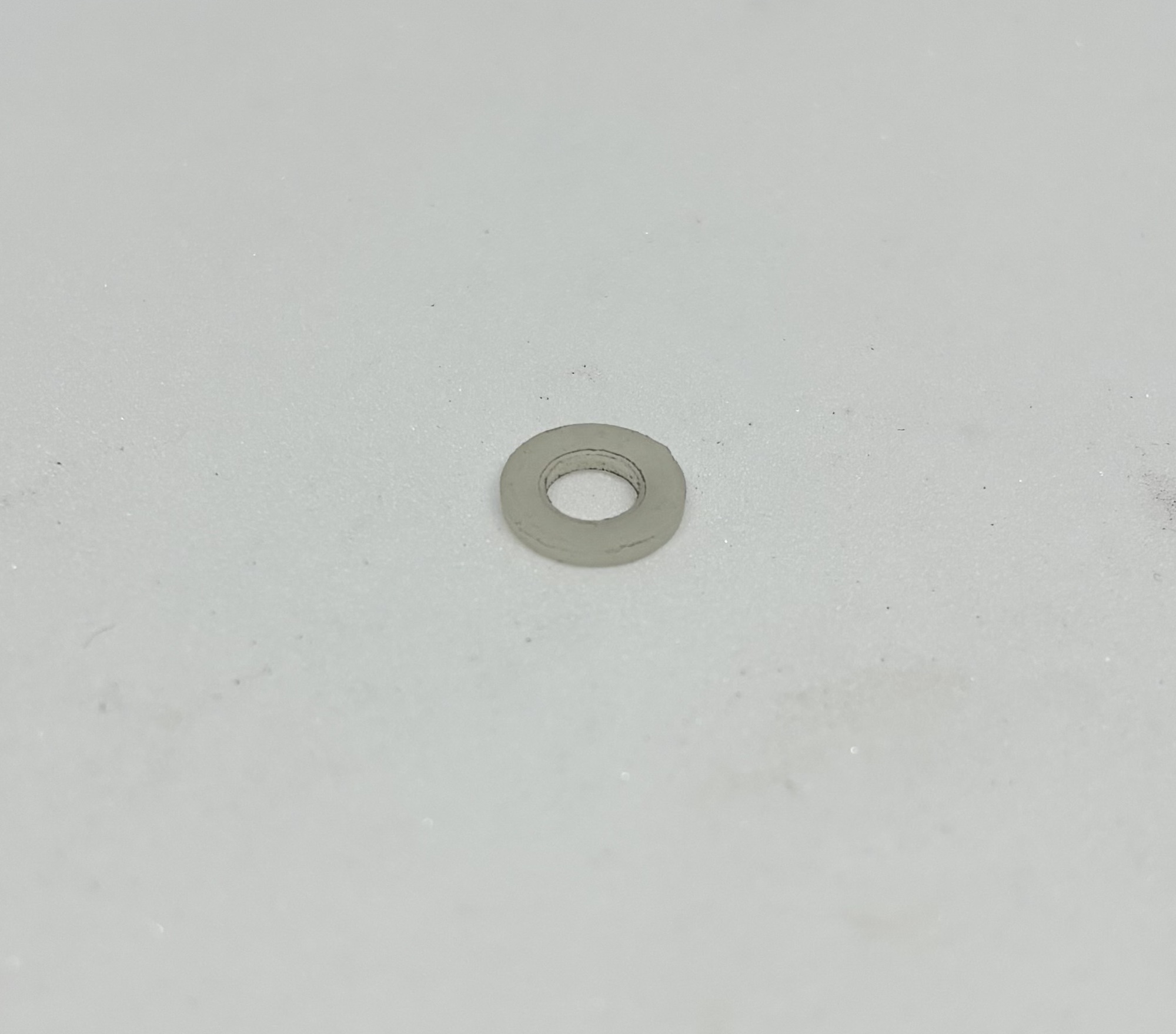
4 pieces M3 nylon washers
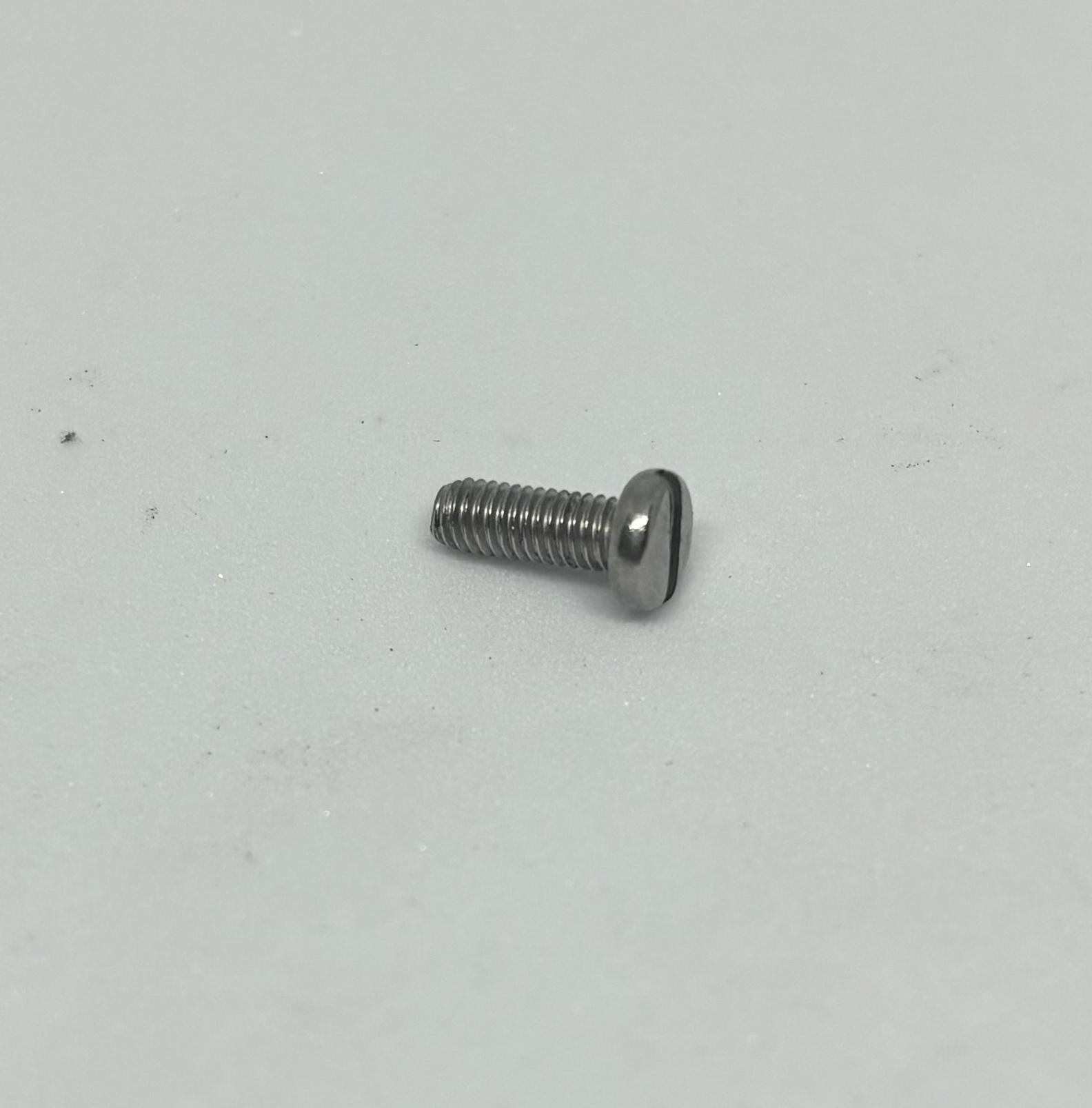
6 pieces M3 x 8 Screws
Screw Driver
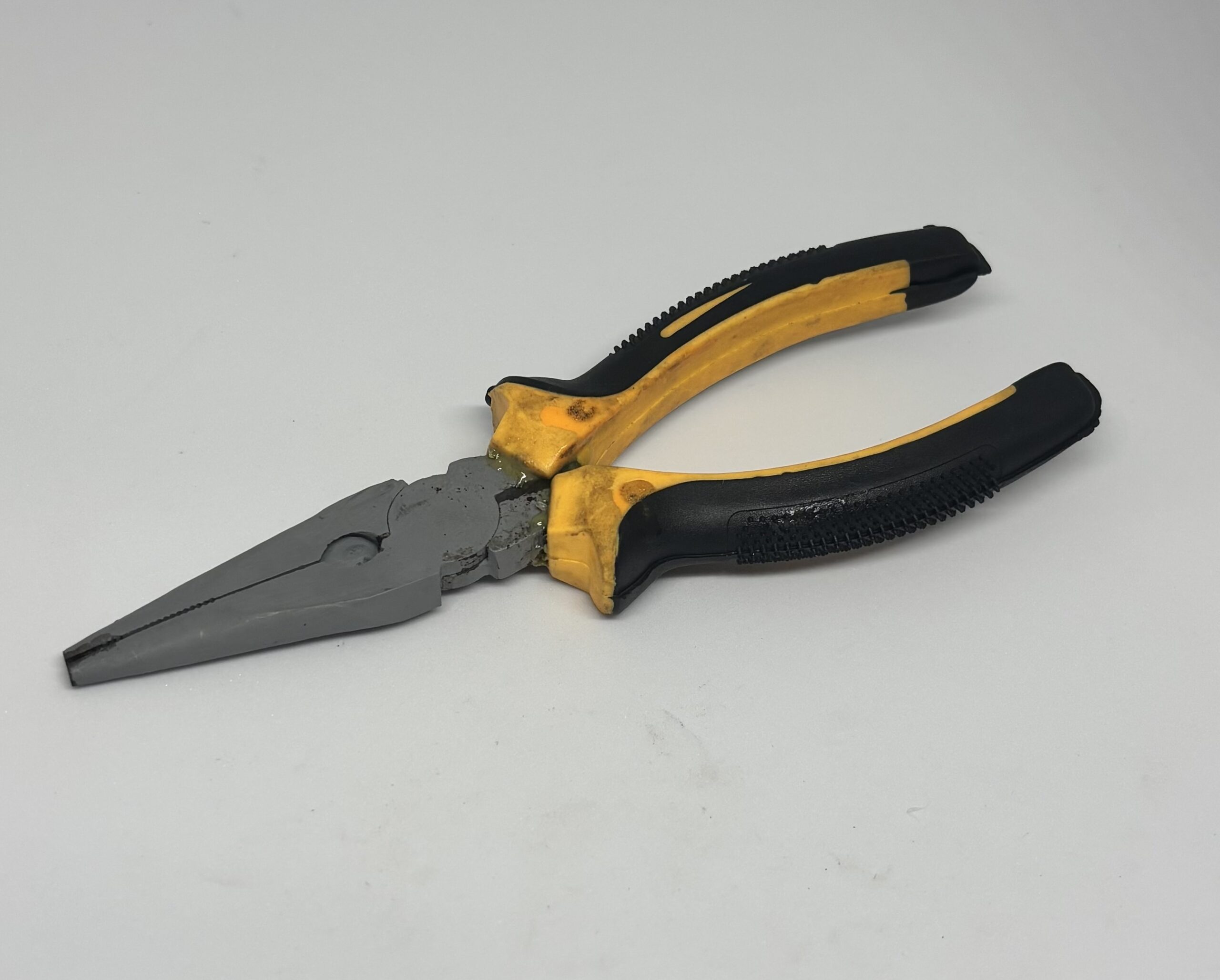
Pliers
Step 1:
Install Mainboard on the body [|]For that, you need to use M3 x 10 screws in the installation holes with Nylon washers touching the Mainboard, [|]To protect the mainboard against scratches and possible short circuits]] , then using flat washers touching body and nylon washers and lock washers after that and then hex nut.]
using screw driver and pliers.
Step 2:
Install the motor on the right side of the body at the side M1 is placed on the MainBoard [|]For that, you need to use M3 x 30 screws with flat washers touching the motor body at one side and the robot body at the other side, then adding a lock washer and then the hex nut in the end, [|]as described here]] , we use the motor inside body method here.]
using 3 M3 x 30 screws, 6 flat washers , 6 lock washers and 6 hex nuts.
Step 3:
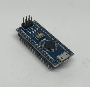
Connect [|]For that, you need to place the Arduino on top of the Arduino pin headers [|]the two big 30 holes pin headers]] , the USB port of it facing the edge of the board, and while you can see the access pins of the pinheader at both sides of the Arduino board, then push it in place to ensure the board is in place.]
the Arduino to the Main board.
Step2:
Plug in the USB cable[|] the USB type B to Micro USB, which you can get from a cellphone charger also]
to the Micro USB port of Arduino and then plug it to the USB port of the computer.
Step3:
Upload [|] Follow this]
the following code to the Arduino.
 int M1A=3;
 int M1B=4;
int speed=50;
void setup() {

pinMode(M1A, OUTPUT);
pinMode(M1B, OUTPUT);

}

void loop() {

  // Forward
digitalWrite(M1B,LOW);
analogWrite(M1A,speed);
delay(1000);

  // Backward
digitalWrite(M1B,HIGH);
analogWrite(M1A,speed);
delay(2000);

//Changing Speed
speed=speed+50;

//Keeping the speed within 50 to 255
if (speed>255)
{
speed=50;
}

}
Step 4:
Connect the motor wires to M1 Screw terminal using the screw driver. The red wire goes to The Terminal of M1 closer to Cellpack, the black wire goes to the terminal further from cellpack.
Step 5:
Install the Cellpack in its place [|]
[using M3 x 8 screws and Lock washers]
and connect the DC power jack Connector to female DC connector on the Mainboard.
Step 6:
Put the 3C and 4C Jumper Caps [|]
[The blue tiny plastic parts in the Main Board that act as a switch and allow the pins to connect to the motor drivers , they are not connecting if you can see one of the pins, to connect them you need to remove them and place it on top of the two pins and push it down.]
in the connecting state so the two corresponding pins connect to each other.
Step 7:
Turn the Cellpack on [|]
[Rocker switch turned towards the ON side and then pressing the Start switch at the top]
and check the movement of the motor, we have two increments, one lasting 1 seconds, motor running forward the other one 2 seconds, motor running backwards. You should notice the one second part starting slow and increasing speed, and the two seconds part running fast at first and slowing down.
Code Explanation
In lines 1 and 2, [|] [We define two integer values that represent the two pins who control our motor driver [|] [A motor driver is an electronic device that controls the speed and direction of an electric motor. It receives signal from Arduino and controls the voltage level and polarity every motor receives .] which we refer to as M1A and M1B. They are pin 3 and pin 4 of Arduino]
In line 3,[|] we define the integer value representing our speed value, which the initial value of it is equal to 50.] .
In line 4,[|] we start the void setup part of our code.] .
In lines 6 and 7,[|] we define our motor driver control pins as OUTPUT.] .
In line 9,[|] we close the void setup part of our code.] .
In line 11,[|] we start the void loop part of our code.] .
In line 13,[|] we signify the part of our code that makes the motor rotate in a direction that would move the robot forward.] .
In line 14,[|] we digital write control pin B, low or feed it with zero volts.] .
In line 15,[|] we analog write control pin A, with the value of speed, which for the start is 50, that will make the motor be fed with a voltage around 1.4 volts, because the potential difference is 1.4-0 volts.] .
In line 16,[|]we make the robot keep doing what it was doing before delay (rotating in the forward direction for 1000 milliseconds or 1 seconds.] .
In line 18,[|] we signify the part of our code that makes the motor rotate in a direction that would move the robot backwards.] .
In line 19,[|] we digital write control pin B, HIGH or feed it with maximum volts available to motor driver, in a fully charged Cellpack that will be around 7 volts.] .
In line 20,[|] we analog write control pin A, with the value of speed, which for the start is 50, that will make the motor be fed with a voltage around 5.6 volts, because the potential difference is 7-1.4 volts.] .
In line 21,[|]we make the robot keep doing what it was doing before delay (rotating in the forward direction for 2000 milliseconds or 2 seconds.] .
In line 24,[|]we add 50 to the value of speed and store it in the variable of speed.Like for the first time the robot running the loop code, from here on, the speed value is 100, until the next time that we change it.] .
In lines 27,28,29 and 30, [|] [we create an “If” statement [|] [ Here the condition in the parenthesis is if the speed value is greater than 255, then it will do what’s in the following brackets , which is changing the value of speed to 255 for the next loop.] to make sure the value of “speed” doesn’t get higher than 255, which is the maximum value we can analog write a pin with.]
In line 32,[|] we close the void loop part of our code.] .
Further Experimentation
Try swapping the pin numbers and see how it affects the direction of the rotation.
Try using higher and lower speed values and see how the motor will work and determine the lowest working speed value for your motors.
Try changing the delay values to see how fast the motor can change rotation.
Practical Usage For our Projects
We can use analog Write function for many occasions, like for 2WD and 4WD motors, to change their speed, rotation directions.
We can also use if statements in a lot of occasions from bipedal robots, line followers , robotic arms, gripper ,… to make our robots more sentient and autonomous.