
In this lesson we will learn how to create a robot that talks by adding the Baby module to the robot and adding a library to Arduino. Our robot then will speak some words in the defined order , so it will be a text to speech machine. If you have done the previous lessons you don’t need to change your robot much, if you have your 2WD robot, use M3 instead of M1 motor by addressing the pins of M3 instead of M1 and changing the motor connections, if you have a 4WD robot, make it 4 on 2 WD by connecting M1 and M3 motors to M3 terminal and M2 and M4 to M4 terminal and change the code accordingly ,and skip steps 1 to 11, except step .
Estimated time: 15 minutes
You will learn about:
Adding A Library
Including a Library
Code Sequence
Components Needed
Main Board | USB Cable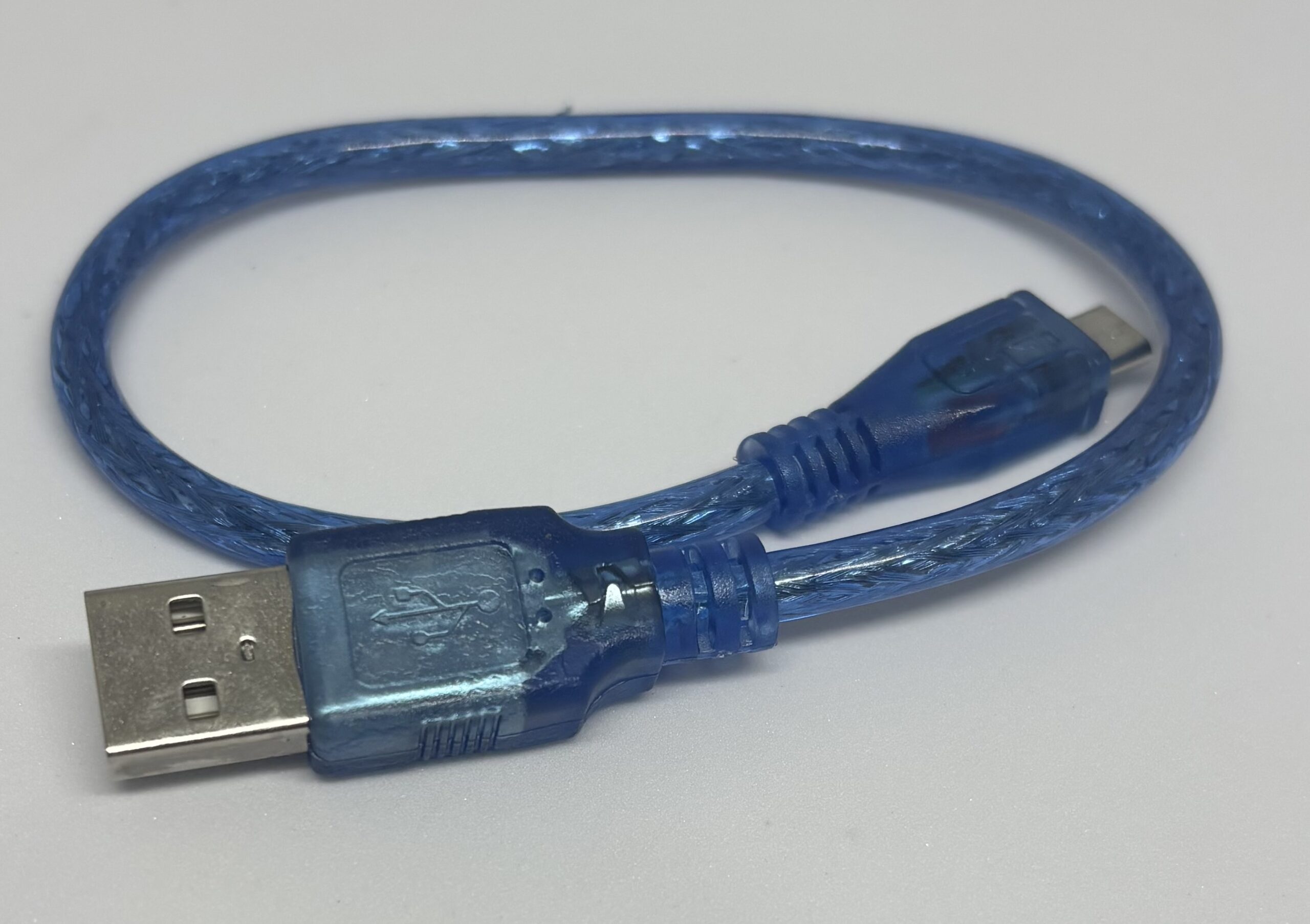 |
Arduino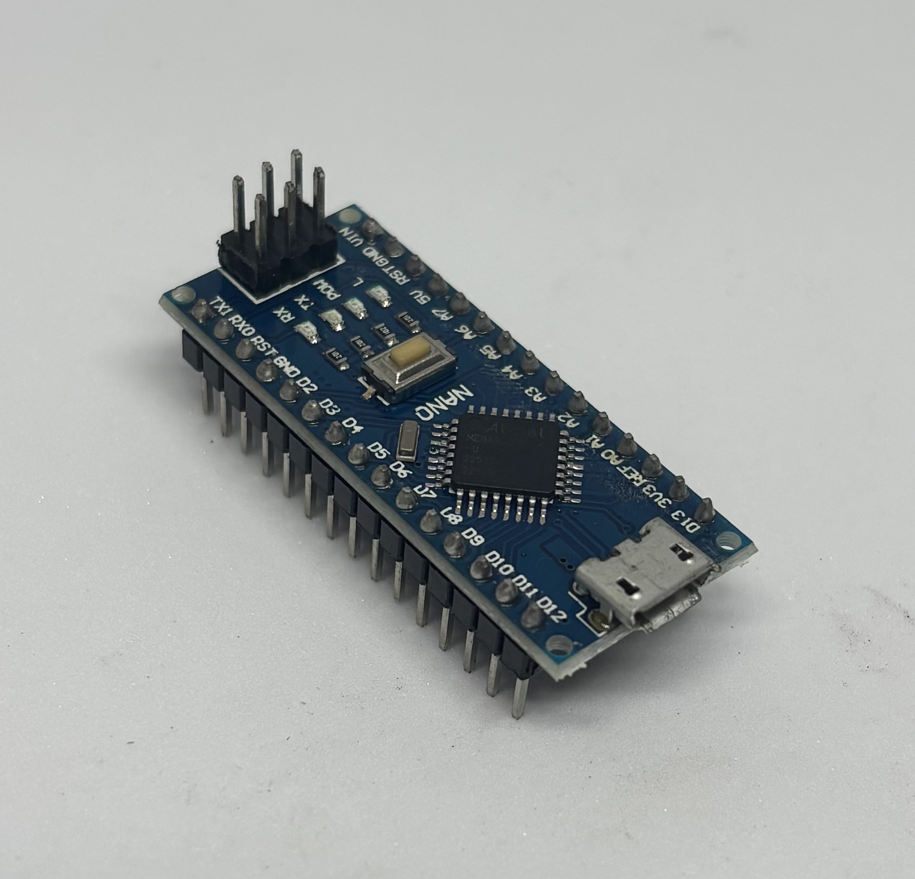 | Body |
Baby Set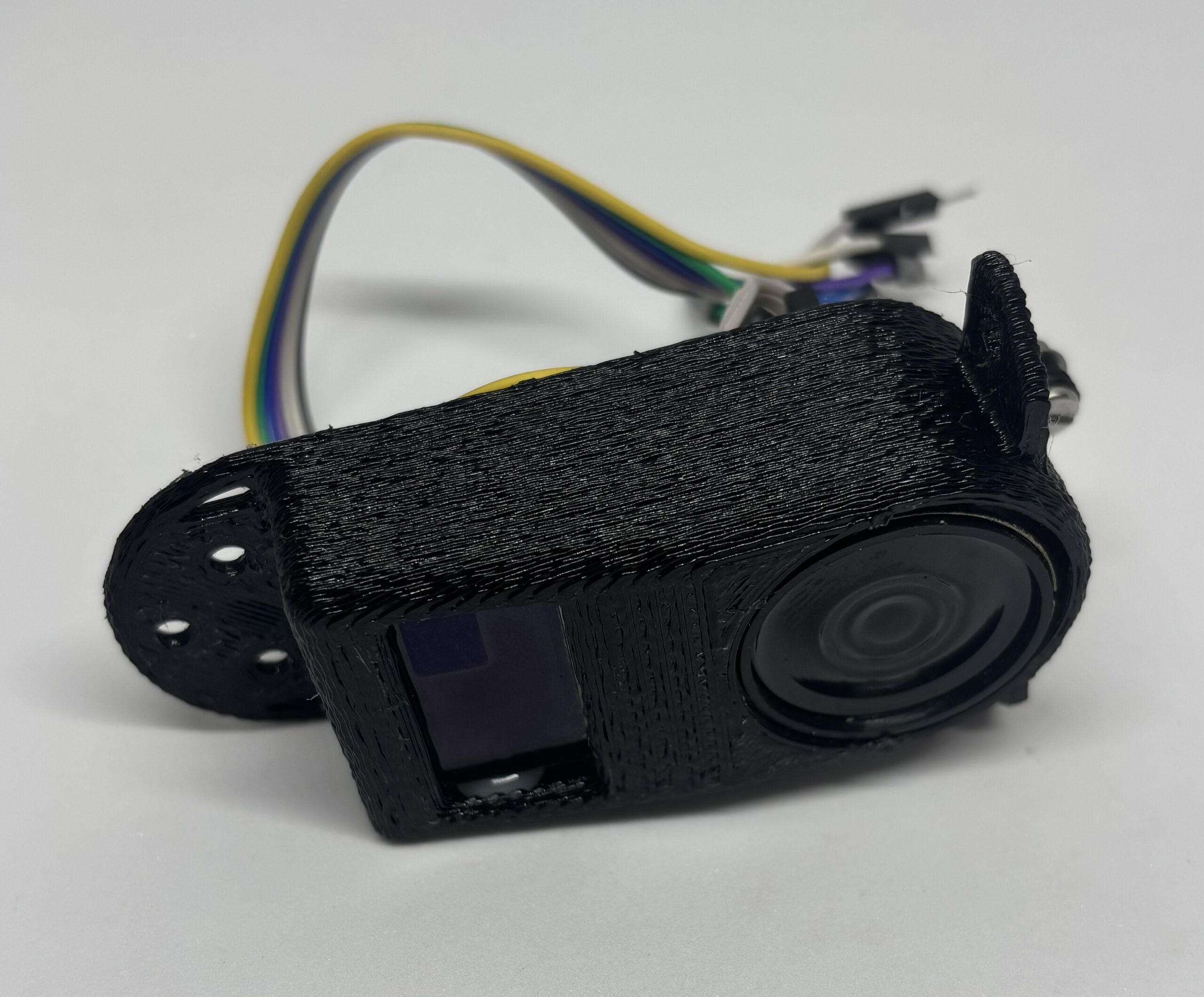 | 3 pieces Female to male wires |
Hood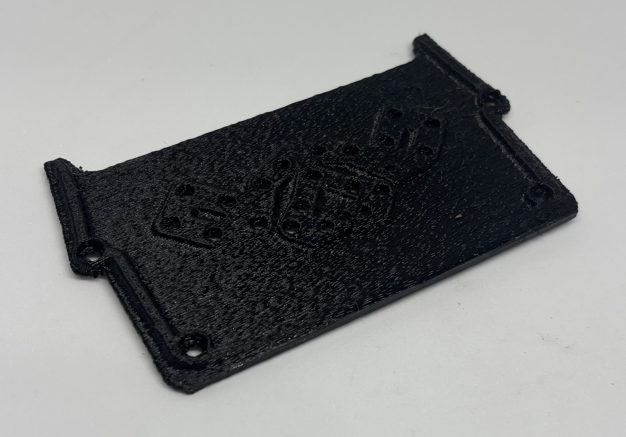 | 10 pieces M3 x 10 Screws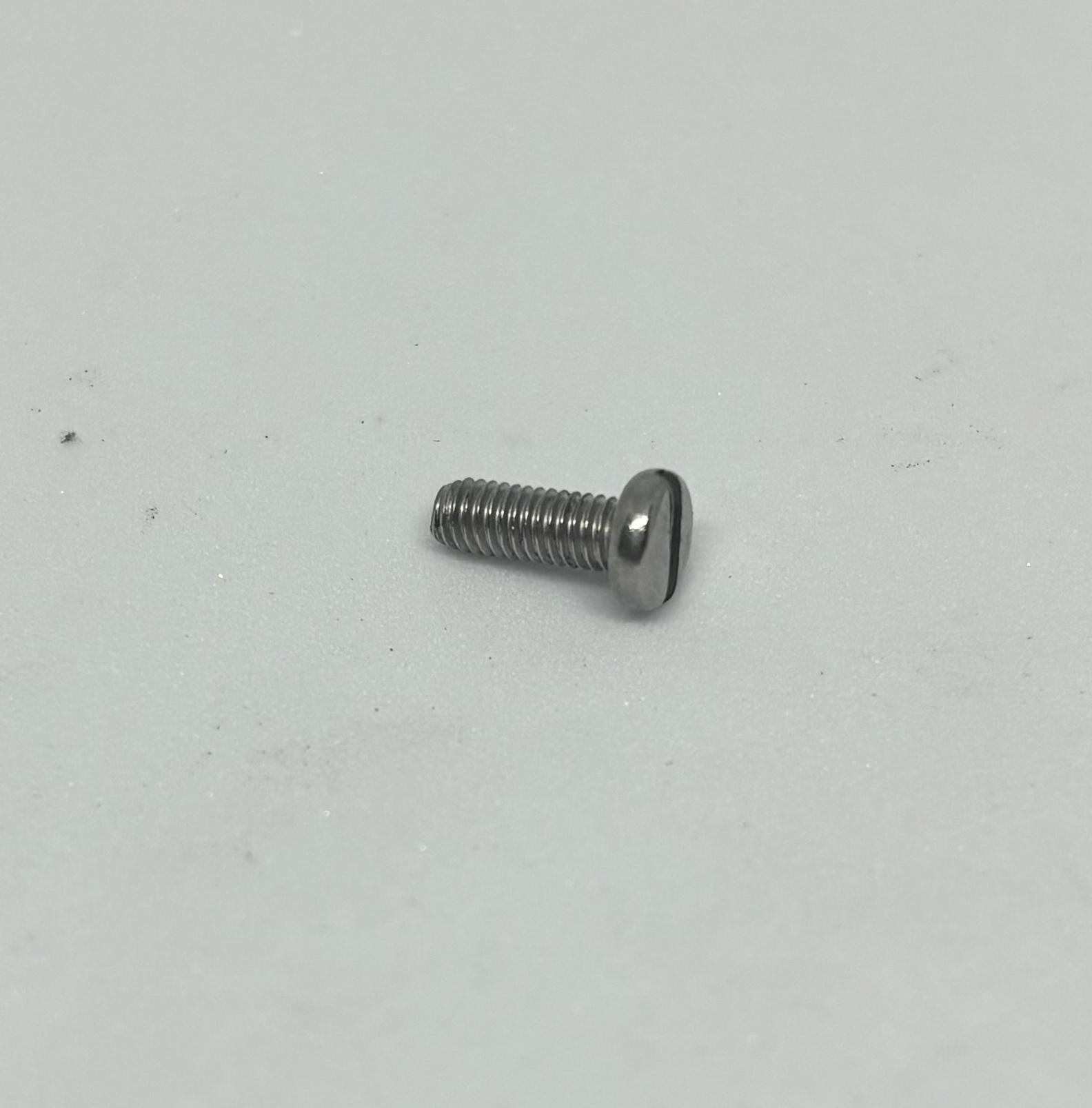 |
| 2 pieces Spacers | 4 pieces M3 Lock Washers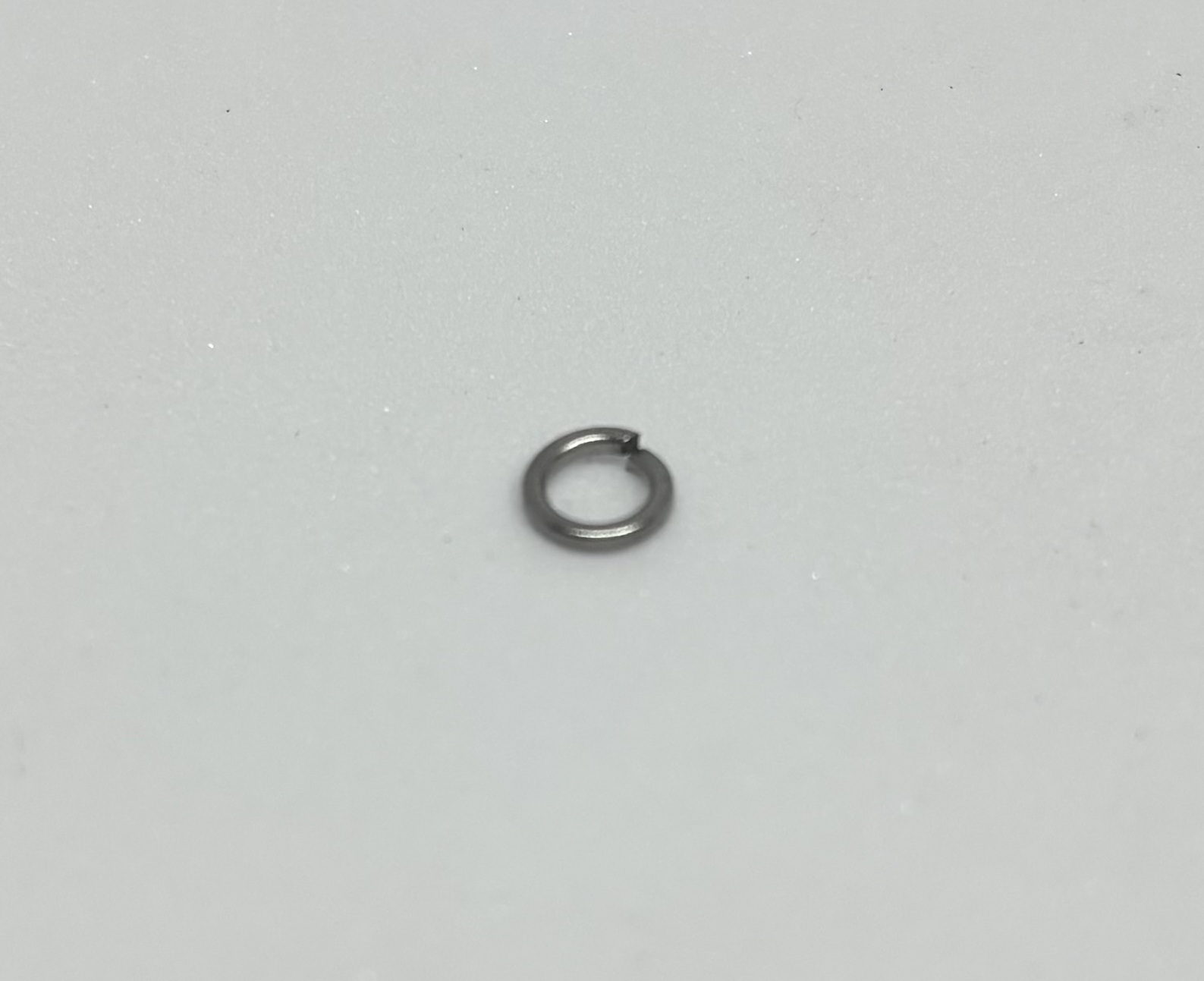 |
2 Pieces M3 Flat Washers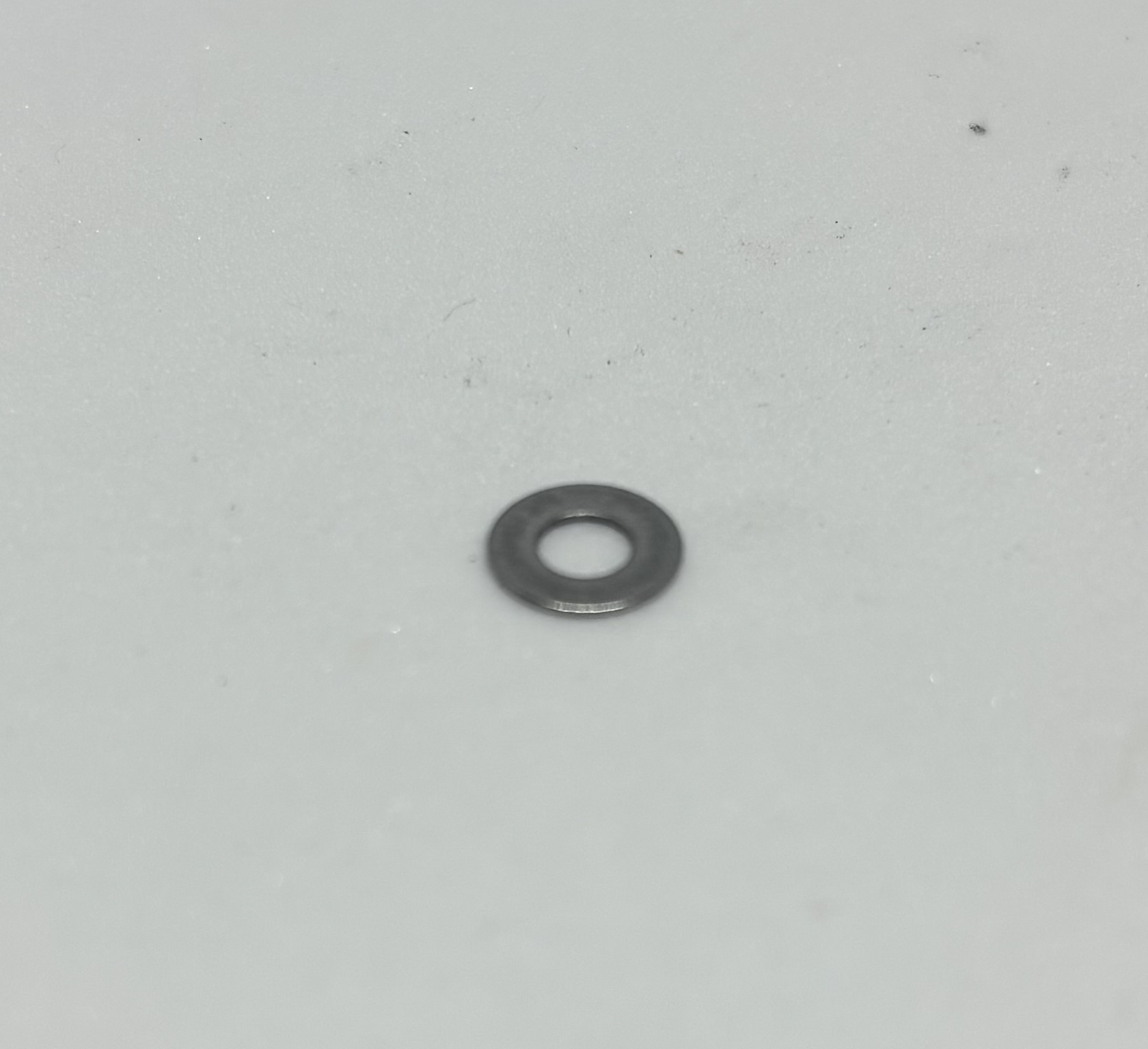 | 2 pieces M4 x 45 screws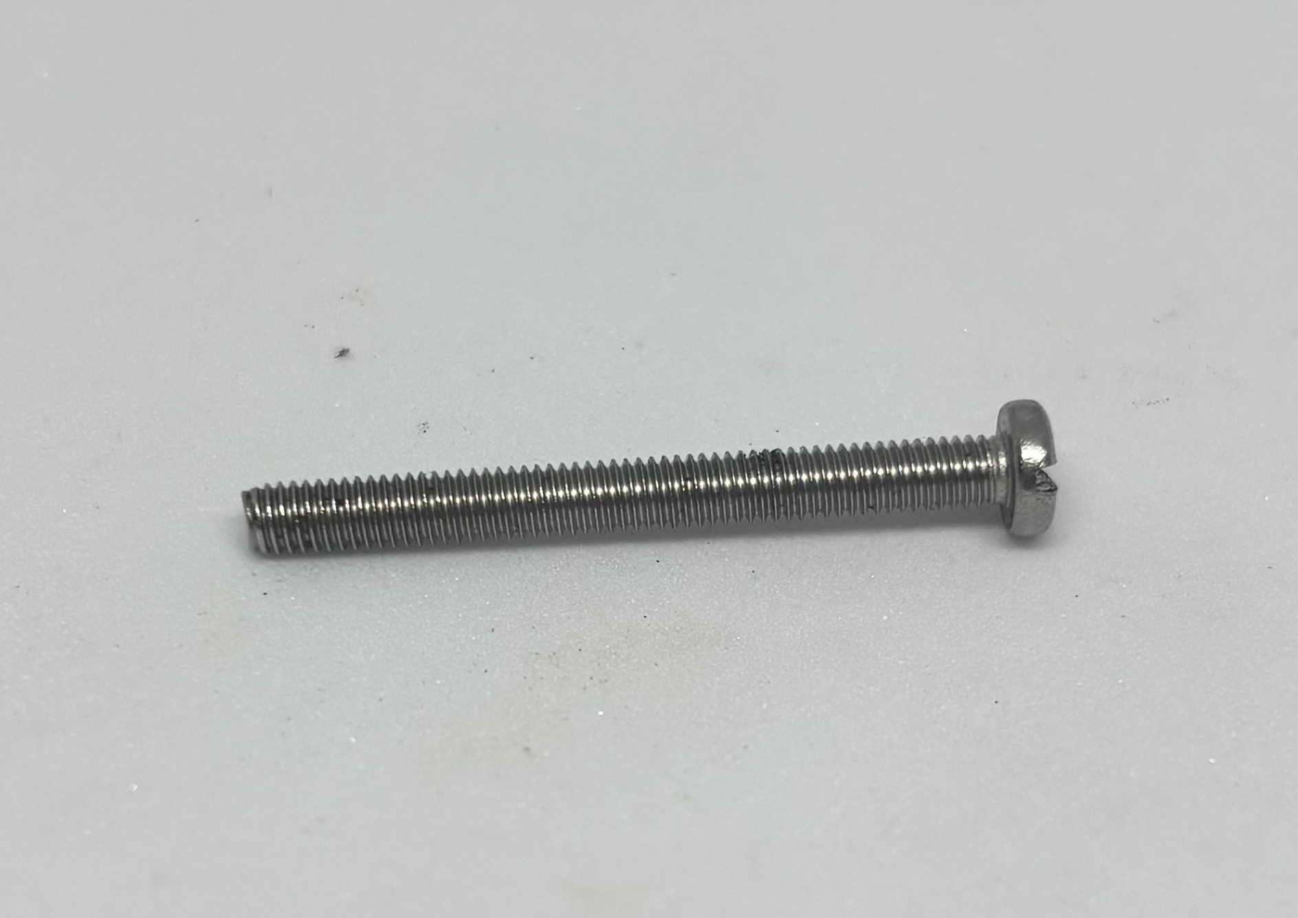 |
8 pieces M4 hex nuts | 4 pieces M4 nylon Washers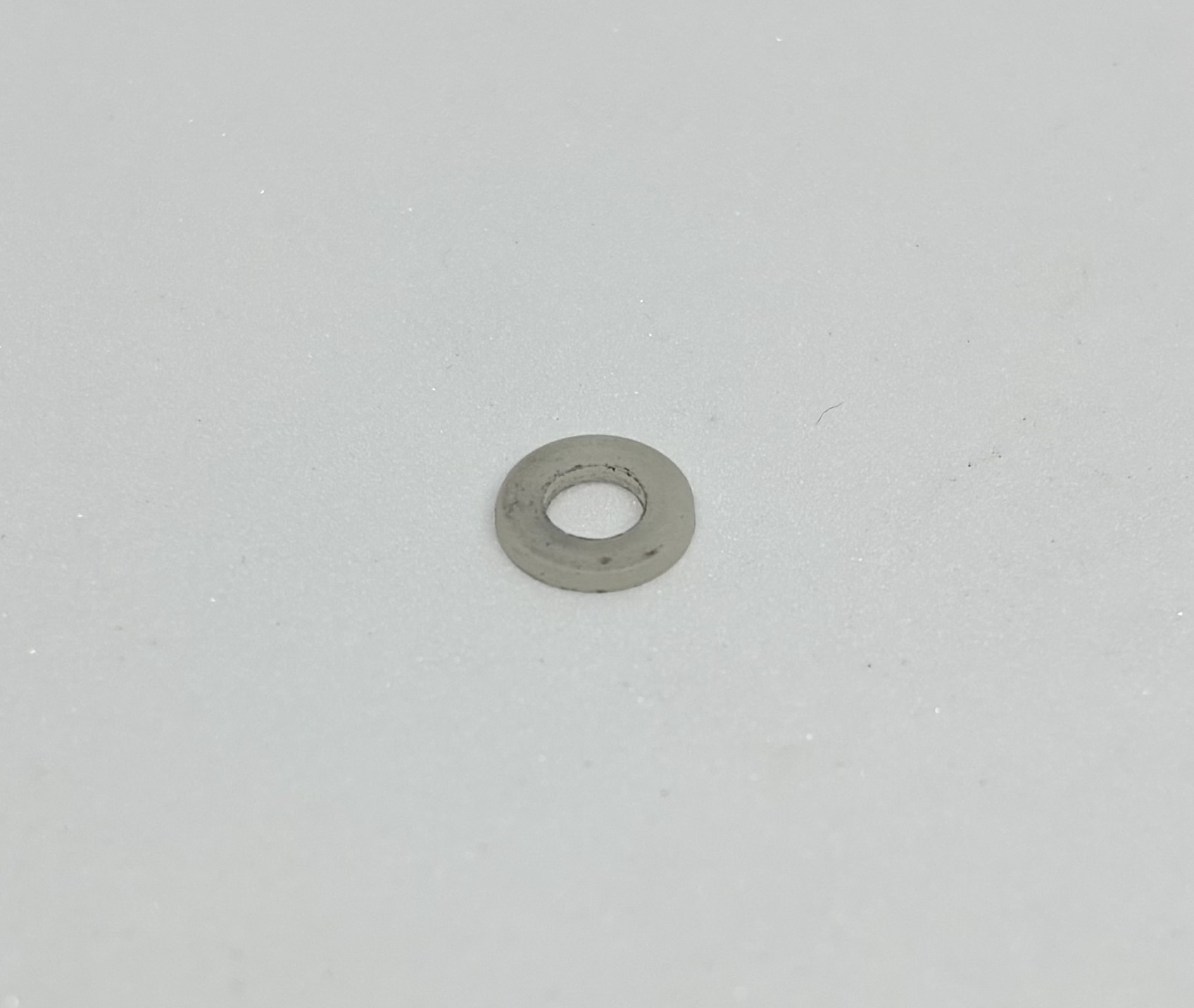 |
2 pieces M4 Lock Washers | 4 pieces M4 Flat Washers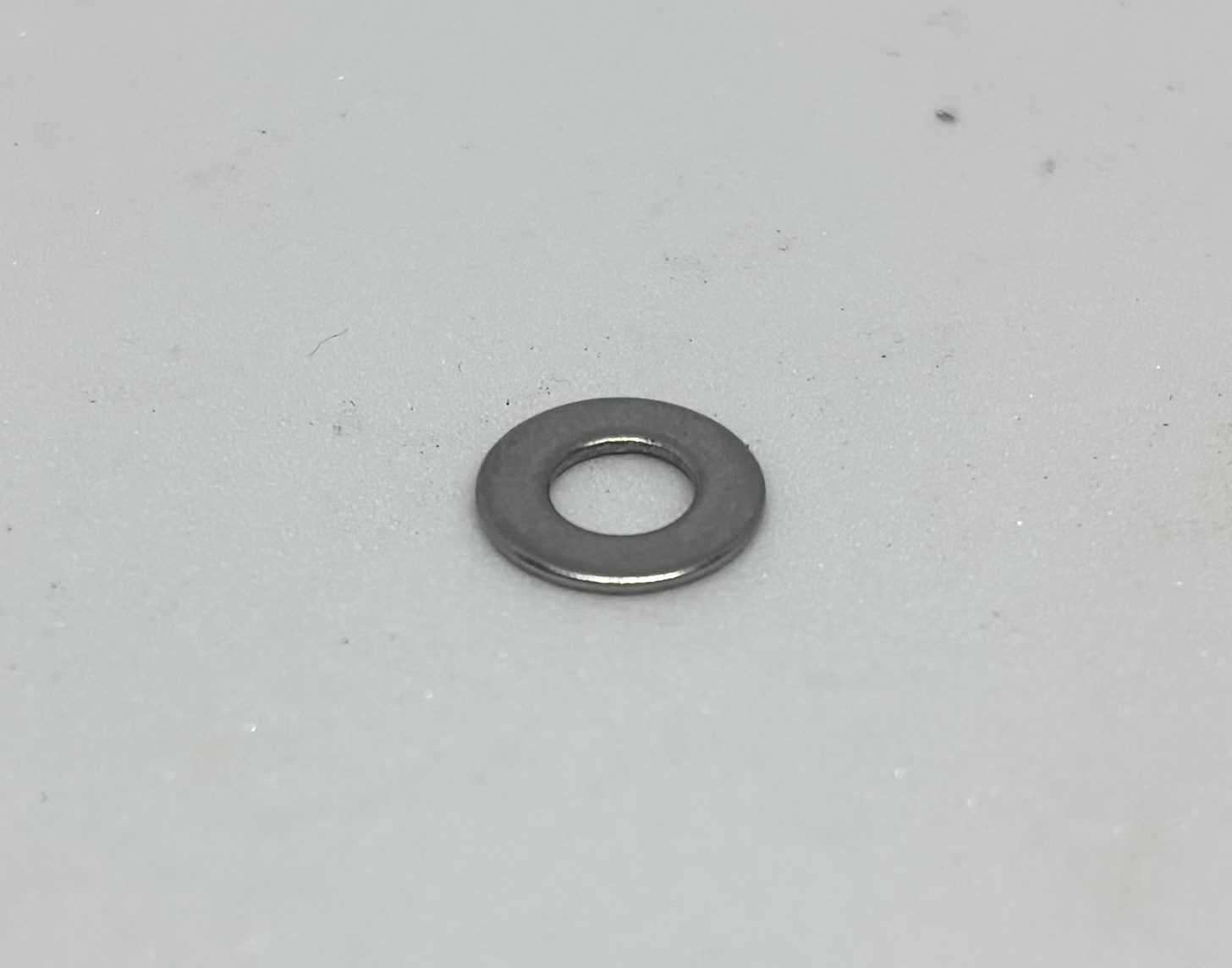 |
Pliers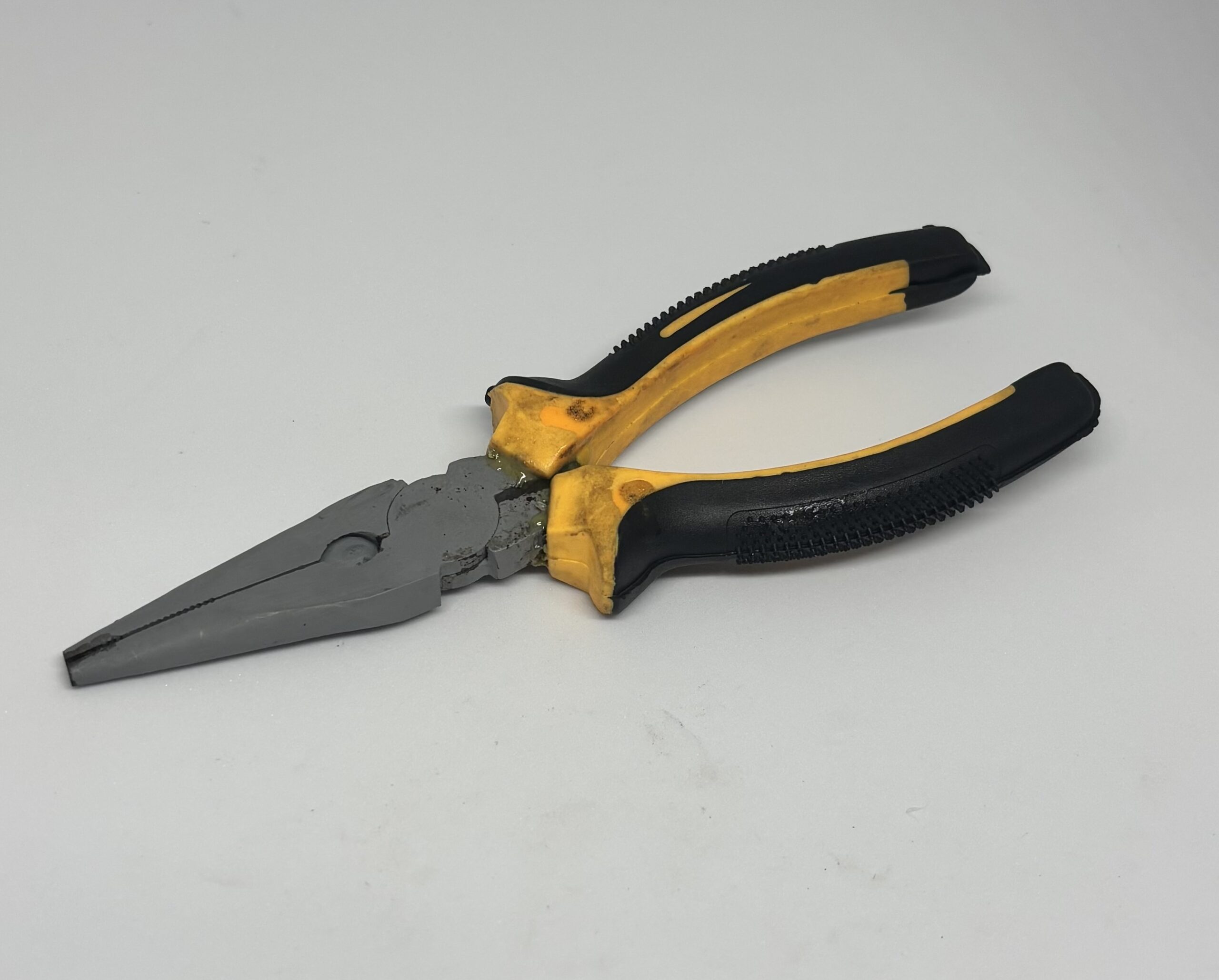 | Screw Driver |
| 6 pieces/ M3 x 30 Screws | |
10 pieces/ M3 Hex Nut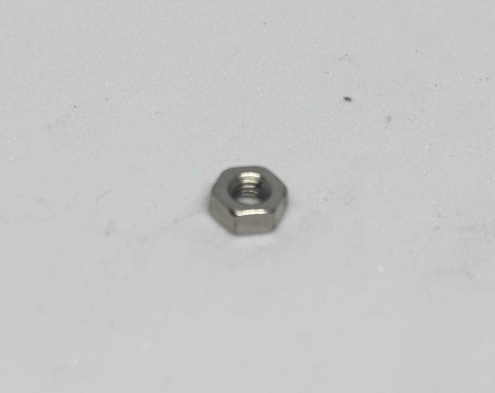 |
Step 1:
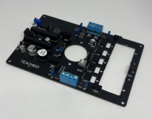
Install Mainboard on the body [|] using screw driver and pliers.
Step 2:
For 2WD, Install the Caster Wheel on the Main Board using M4 Screws .
Step 3:
Install the motors on the both sides of the body [|] using 6 M3 x 30 screws, 12 flat washers , 6 lock washers and 6 hex nuts.
Step 4:
Make sure the Jumper cap of 3C is disconnected so pin 3 remains isolated.
Step 5:
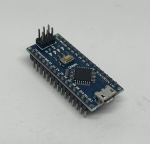
Connect [|] the Arduino to the Main board.
Step 5:
Plug in the USB cable[|] to the Micro USB port of Arduino and then plug it to the USB port of the computer.
Step 6:
Add the “Talkie” Library [|] to the Arduino IDE.
Step 7:
Upload [|] the following code to the Arduino.
// Talkie library
// Copyright 2011 Peter Knight
// This code is released under GPLv2 license.

//
// Welcome to the Talkie library examples.
//
// Talkie is a speech synthesiser that works from a fixed vocabulary.
//
// There are hundreds of words in the 'Vocabulary' examples.
//

/*
 * Voice PWM output pins for different ATmegas:
 *  ATmega328 (Uno and Nano): non inverted at pin 3, inverted at pin 11.
 *  ATmega2560: non inverted at pin 6, inverted at pin 7.
 *  ATmega32U4 (Leonardo): non inverted at pin 10, inverted at pin 9.
 *  ATmega32U4 (CircuitPlaygound): only non inverted at pin 5.
 *
 *  As default both inverted and not inverted outputs are enabled to increase volume if speaker is attached between them.
 *  Use Talkie Voice(true, false); if you only need not inverted pin or if you want to use SPI on ATmega328 which needs pin 11.
 *
 *  The outputs can drive headphones directly, or add a simple audio amplifier to drive a loudspeaker.
 */
#include <Arduino.h>

#include "Talkie.h"
#include "Vocab_US_Large.h"

Talkie voice;

void setup() {

    voice.say(sp2_START);
    voice.say(sp2_OPERATOR);
    voice.say(sp2_IS);
    voice.say(sp2_UP);
    voice.say(sp2_A);
    voice.say(sp2_B);
    voice.say(sp2_C);
    voice.say(sp2_1);
    voice.say(sp2_2);
    voice.say(sp2_3);
    voice.say(sp2_U);
    voice.say(sp2_B);
    voice.say(sp2_SAFE);
    voice.say(sp2_OVER);
}

void loop() {
}
Step 8:
Remove the USB cable from the USB port of Arduino.
Step 9:
Connect the motor wires to M3 and M4 Screw terminal using the screw driver. The red wire goes to The Terminals closer to Cellpack, the black wires goes to the terminals away from Cellpack.
Step 10:
Install the baby set on top of the M4 x 45 screws using M4 nuts and use the female to male wires to connect the wire from pin 3 of Arduino to pin “S” of the amplifier module in the Baby set, “5V” pin of Arduino to “VCC” pin of the amplifier module and “GND” pin of Arduino to “GND” pin of the amplifier module.
Step 11:
Install the spacers by removing the two screws at the hood part of the robot and placing the spacers on top and fastening the screws from beneath having the Nylon washers touching the Mainboard and flat washer and spring washers under it .
Step 12:
Install the Hood on the body with M3 x 10 screws.
Step 13:
Install the Cellpack in its place [|] and connect the DC power jack Connector to female DC connector on the Mainboard.
Step 14:
Put the 2C , 4C and 5C Jumper Caps [|] in the connecting state so the two corresponding pins connect to each other, make sure 3C jumper cap is disconnecting.
Step 15:
Turn the Cellpack on [|] and check the voice of the robot, we have this code running only once because it’s in the void setup part , so if you want to hear that again press the reset button.
Congratulations! You have your own Robot now.
Step 16:
If the Sound isn’t loud enough, use the screwdriver to turn the potentiometer on the amplifier module at the back of the Baby set to adjust volume.
Code Explanation
- In lines 13 to 24, [|]
- In line 25 ,[|] .
- In line 27,[|] .
- In line 28,[|] .
- In line 30,[|] .
- In lines 34 to 47,[|] .
- In line 50 to 51,[|] .
Further Experimentation
- Try cutting everything in void setup code , and pasting it in the void loop part and upload the code and see what happens.
- Try using delays to make the speech more natural.
- Try to mix this code with the 2WD robot or 4WD robot to make your robot report it’s heading.
- Try building your own sentences picking the file names from the following list and pasting in the code:
To see the list click [Here]
Practical Usage For our Projects
- We will use the talking robot wherever we need our robot to have a voice but don’t want to or can’t use the card reader module in the robot, also there are times that we want a notification without using display or connecting Arduino to computer, we can use this configuration there.