In this lesson we will learn how to read a pin`s status when it works as an input for Arduino. We will use the internal circuitry of the robot and a male to male wire to read the status of a pin in the serial monitor of Arduino IDE.
Estimated time: 5 minutes
You will learn about:
Digital Read
Integer Data Type
Serial Monitor
Pinmode Input
Components Needed
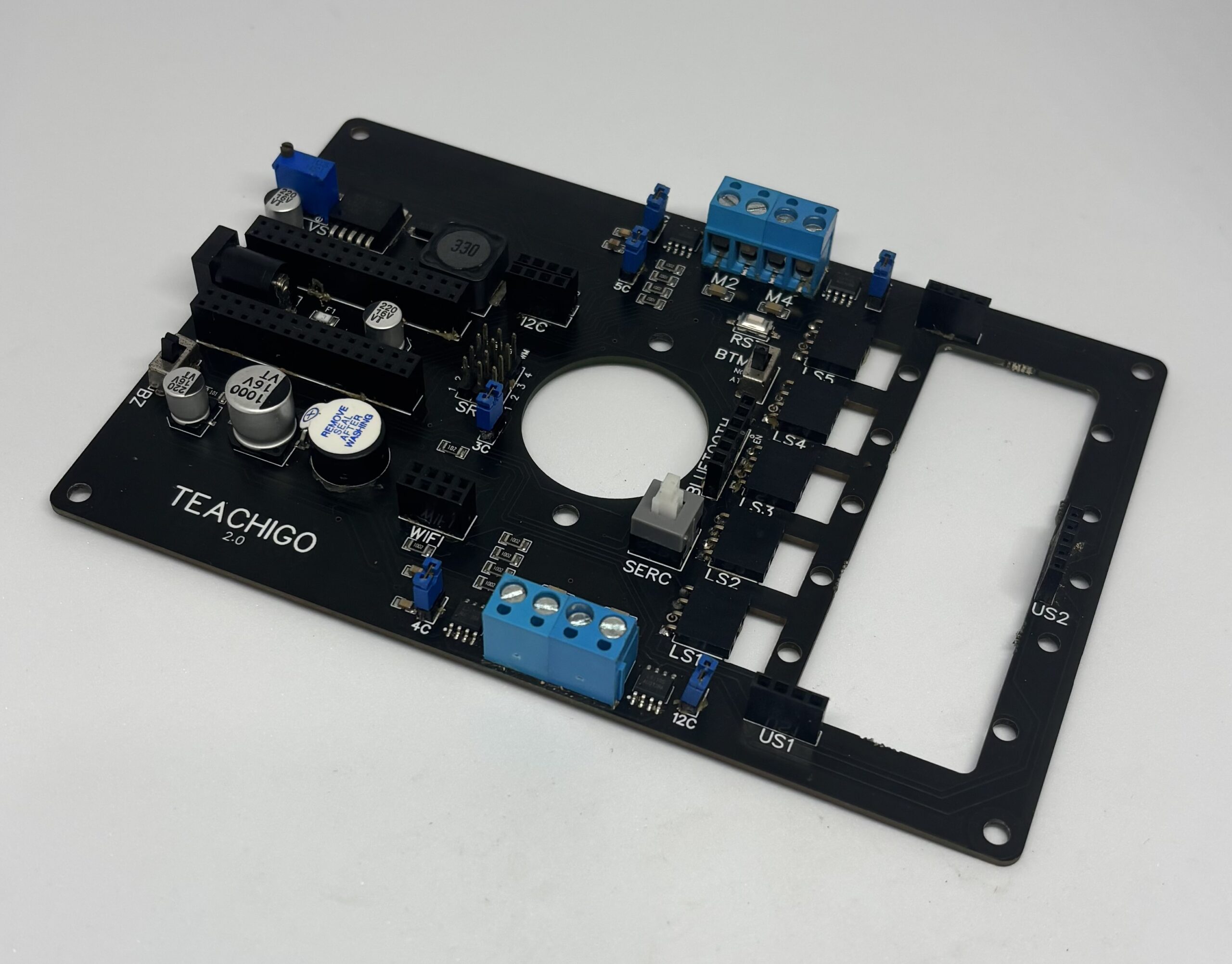
Main Board
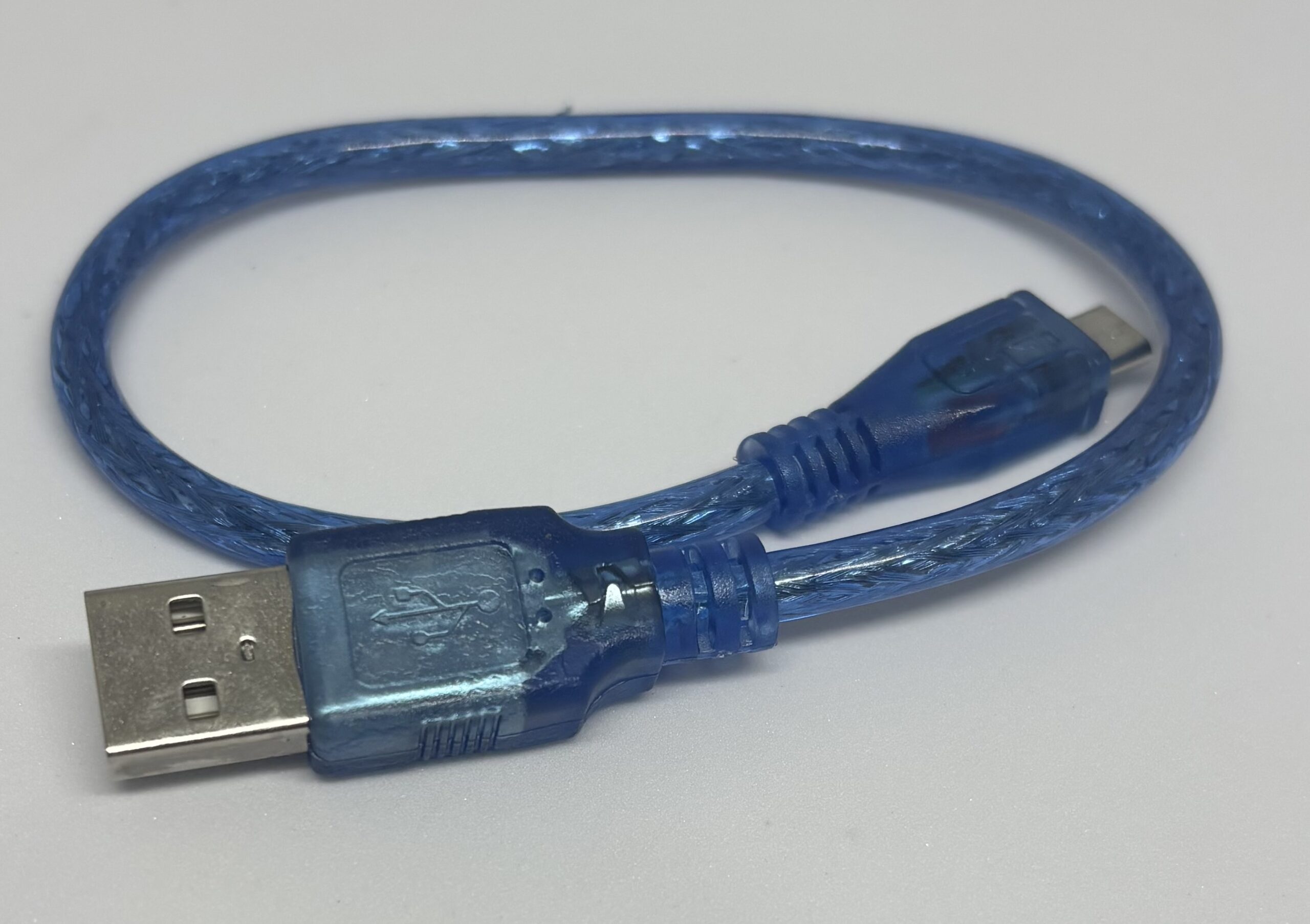
USB Cable
Male to Male wire
Connections
Step1
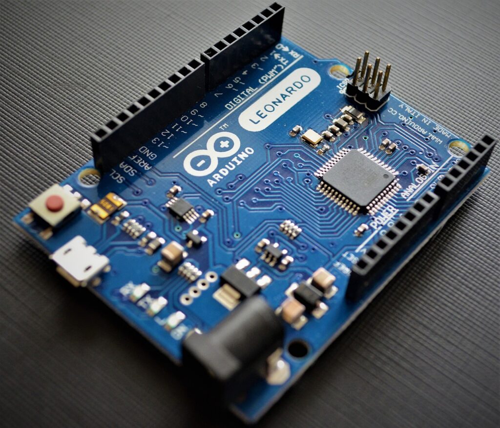
Connect [|]For that, you need to place the Arduino on top of the Arduino pin headers [|]the two big 30 holes pin headers]] , the USB port of it facing the edge of the board, and while you can see the access pins of the pinheader at both sides of the Arduino board, then push it in place to ensure the board is in place.]
the Arduino to the Main board.
Step2:
Plug in the USB cable[|] the USB type B to Micro USB, which you can get from a cellphone charger also]
to the Micro USB port of Arduino
Step3:
Upload [|] Follow this]
the following code to the Arduino.[This code can be found in Files/Examples/01Basics/DigitalReadSerial in Arduino IDE]
int Button = 2;
// the setup routine runs once when you press reset:
void setup() {
  // initialize serial communication at 9600 bits per second:
  Serial.begin(9600);
  // make the pushbutton's pin an input:
  pinMode(Button, INPUT);
}

// the loop routine runs over and over again forever:
void loop() {
  // read the input pin:
  int buttonState = digitalRead(Button);
  // print out the state of the button:
  Serial.println(buttonState);
  delay(1);  // delay in between reads for stability
}
Step 4:
Connect the male to male wire between expansion pin [|][The immediate header pin beside each Arduino pin on the motherboard]2 of Arduino and EN pin of the Bluetooth header [|][Header pins are where a male pin of a device or male wire is connected.].
Step 5:
While the Arduino is plugged in, open the Serial Monitor [|][in Arduino IDE, select from the upper-right icon, or go to Tools > Serial Monitor, or equivalently press Ctrl+Shift+M; Serial Monitor allows us to see the Arduino’s output while it’s working or allows us to send commands to other devices connected to Arduino.]
and make sure the Baud Rate [|][the rate at which information is transferred in Serial Monitor.]
is set to 9600.
Step 6:
With switching the BT MD switch beside the bluetooth header, you can see the numbers become 0 and 1. That`s the values that pin 2 receives.
Code Explanation
In line 1, [|]We define an integer value
[|]Integers are our primary data-type for number storage.
In our Arduino, they store numbers from -32,768 to 32,767 with no digits.
that represents the pin we want to use for reading digital values
[|]values that are either 0 or 1 representing 0 volts or 5 volts]],
or we give our pin a name.
In line 2, 4, 6, 10, 12 and 14, [|] we have a line that starts with ‘//’ , any line with that at the start, doesn`t get read by the microcontroller, we use them for commenting or explaining or turning one line ON and OFF.] .
In line 3,[|] we define the start of our Void setup part of the code which runs only once when we turn the robot ON.] .
In line 5,[|] we begin a serial connection in order to interact with our arduino while it’s working and we define our Baud rate as 9600, that’s why we have to make sure in Serial Monitor , the Baud Rate is also 9600.] .
In line 7,[|]we use the pinMode to define our pin (here pin 2) as INTPUT which enables us to read HIGH or LOW values in it. (Our possible terms for pinMode in our lessons are OUTPUT, INPUT , INPUT_PULLUP)(also note that we had set a name for our pin before (Button) and we recalled it here by it’s name.] .
In line 8,[|]we close the void setup part of the code.] .
In line 9,[|]we don’t have anything written, the Arduino doesn’t read that line, so we can use empty lines to separate parts of our code for decluttering and easier finding those parts.] .
In line 11,[|] we start our void loop part of the code , which runs repeatedly in a loop as long as we power our Arduino.] .
In line 13, [|]we define an integer value [|]Integers are our primary data-type for number storage. In our Arduino, they store numbers from -32,768 to 32,767 with no digits. with the name of buttonState which stores digital read values [|]values that are either 0 or 1 representing 0 volts or 5 volts]]
In line 15,[|] we print in Serial Connection, to be shown in Serial Monitor, the value that our pin reads and stores in buttonState ,showing one value in every line, using Serial.println function .] .
In line 16,[|] we have a delay of 1 Milliseconds .] .
In line 12,[|] we define the end of the Void loop part of our code.] .
Further Experimentation
Try adding two slashes(//) at the start of the line who defines the pin as INPUT (line7) and see if that affects the function.
Try changing the Baud Rate in the Serial Monitor and see what happens. Also use higher and lower values in the code and see how it affects the results in Serial Monitor.
Try turning “Serial.println” function to “Serial.print” function and see how if affects showing the results in the Serial Monitor.
Practical Usage For our Projects
We can use digital Read function To have a switch anywhere in our robot. as an example we can use that to determine when the gripper of our robotic arm has grabbed something.
We can also read the digital output values of our sensors with that . Sensors like line sensor, Ultrasonic sensor,…
For our Ultrasonic sensor we use digital Read to measure the time of travel for our pulse to measure distance.