
In this lesson we will learn how to read an analog Voltage in two different situations and learn about it`s different functions . We will use this function to read the voltage value in a setup very similar to our digital Read setup and also we will use that knowledge to detect the lines with our line sensor.
Estimated time: 10 minutes
You will learn about:
Analog Read
Integer Data Type
Float Data Type
Line Sensor
Components Needed
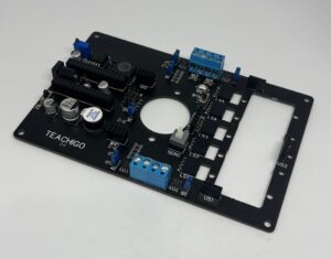
Main Board | USB Cable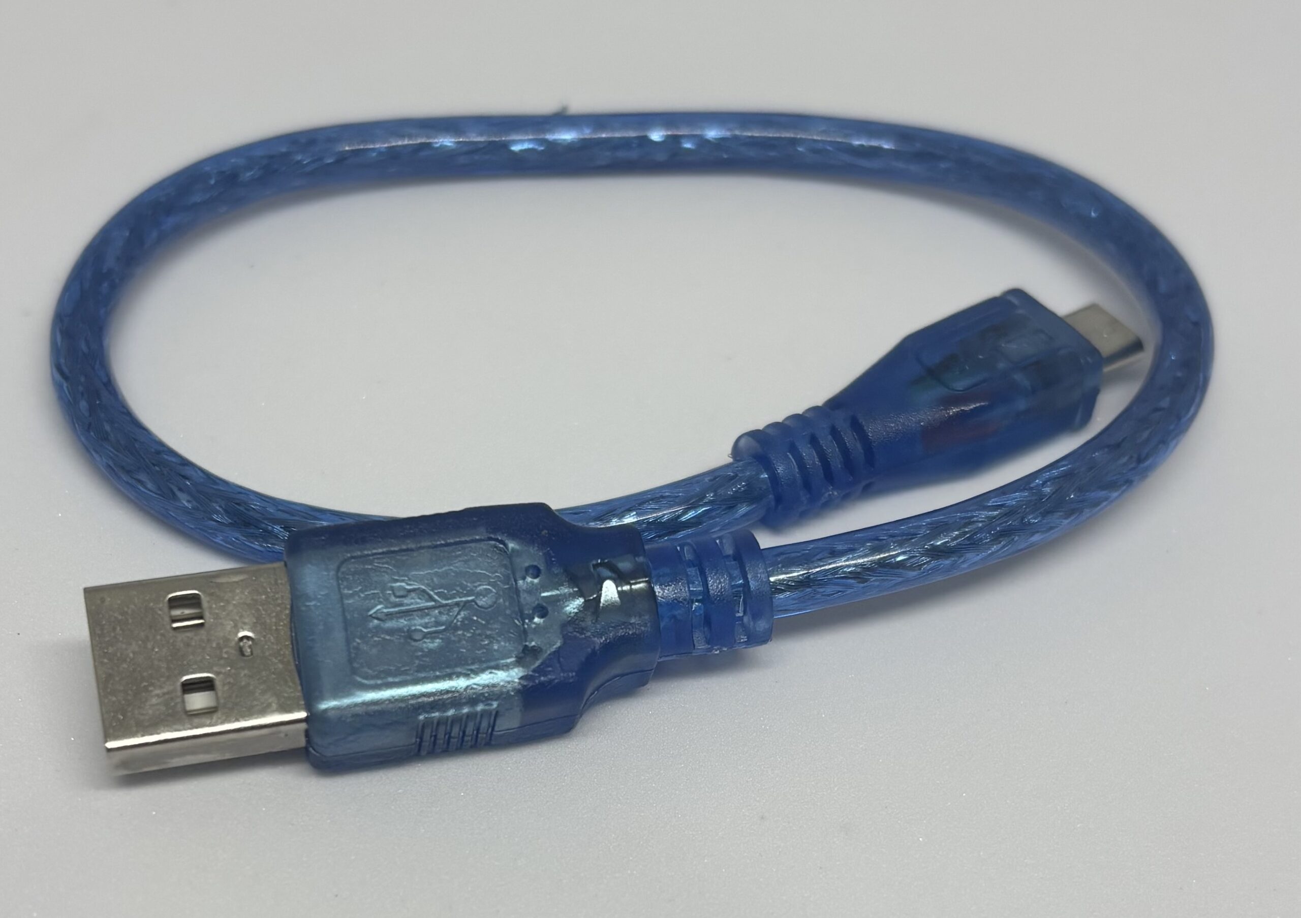 |
Male to Male wire | Line Sensor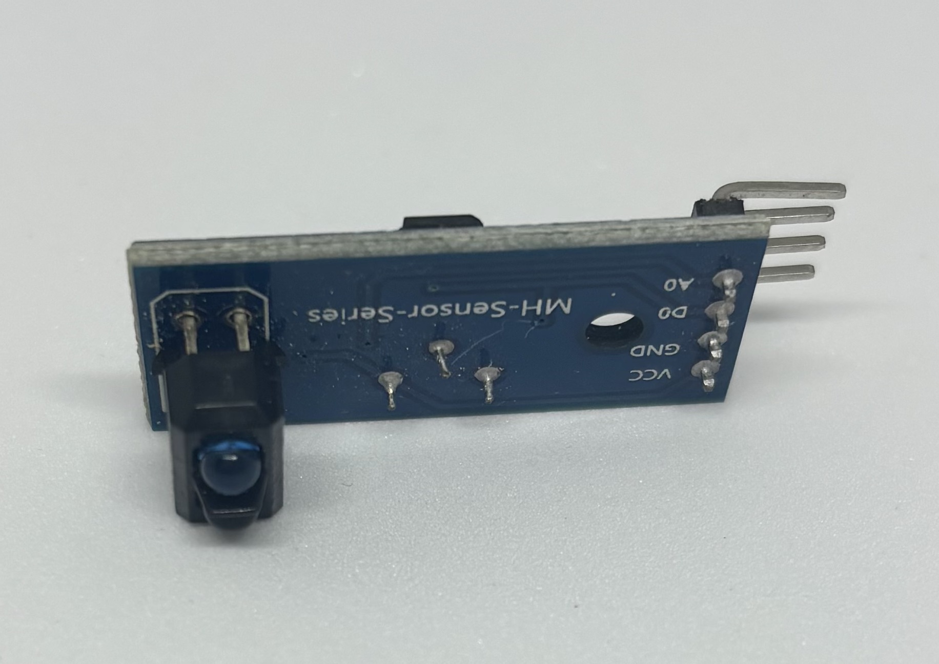 |
Connections
Step1
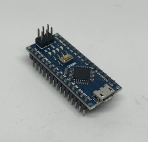
Connect [|] the Arduino to the Main board.
Step2:
Plug in the USB cable[|] to the Micro USB port of Arduino
Step3:
Upload [|] the following code to the Arduino.[This code can be found in Files/Examples/01Basics/ReadAnalogVoltage in Arduino IDE]
// the setup routine runs once when you press reset:
void setup() {
  // initialize serial communication at 9600 bits per second:
  Serial.begin(9600);
}

// the loop routine runs over and over again forever:
void loop() {
  // read the input on analog pin 0:
  int sensorValue = analogRead(A0);
  // Convert the analog reading (which goes from 0 - 1023) to a voltage (0 - 5V):
  float voltage = sensorValue * (5.0 / 1023.0);
  // print out the value you read:
  Serial.println(voltage);
}
Step 4:
Connect the male to male wire between access pin [|]A0 of Arduino and EN pin of the Bluetooth header [|] .
Step 5:
While the Arduino is plugged in, open the Serial Monitor [|] and make sure the Baud Rate [|] is set to 9600.
Step 6:
With switching the BT MD switch beside the bluetooth header, you can see the numbers become around 0 and 3.3 volts. That`s the values that pin A0 measures.
Code Explanation
- In lines 1, 3, 7, 9, 11 and 13, [|] .
- In line 2,[|] .
- In line 4,[|] .
- In line 5,[|] .
- In line 8,[|] .
- In line 10, [|]
- In line 11,[|] .
- In line 12, [|]
- In line 14,[|] .
- In line 15,[|] .
Further Experimentation
- Try adding a number in the parenthesis in line 14 where we print our float value like
Serial.println(voltage);and see how the numbers will be shown. that will display the float numbers with more digits and accuracy. - Try adding a delay line before line 15 like
delay(100);and see how that affects the performance.
- Don’t change the circuit, add one of the line sensor modules to the circuit ,installing that in LS1 header. Upload the following code:
void setup() {
  // initialize serial communication at 9600 bits per second:
  Serial.begin(9600);
}

// the loop routine runs over and over again forever:
void loop() {
  // read the input on analog pin 0:
  int sensorValue = analogRead(A7);

  // Convert the analog reading (which goes from 0 - 1023) to a voltage (0 - 5V):
  float voltage = sensorValue * (5.0 / 1023.0);
  // print out the value you read:
  Serial.println(voltage);
}
- Notice how the value changes when you move the line sensor on a paper and compare the results on black and white surfaces.
- Now again without changing the circuit, upload the following code:
void setup() {
  // initialize serial communication at 9600 bits per second:
  Serial.begin(9600);
}

// the loop routine runs over and over again forever:
void loop() {
  // read the input on analog pin A0:
  int sensorValue1 = analogRead(A0);
  delay(5);
    // read the input on analog pin A7:
    int sensorValue2 = analogRead(A7);

  // Convert the analog reading (which goes from 0 - 1023) to a voltage (0 - 5V):
  float voltage1 = sensorValue1 * (5.0 / 1023.0);
    float voltage2 = sensorValue2 * (5.0 / 1023.0);

  // print out the value you read:
  Serial.print(voltage1);
    Serial.println(voltage2);
}
- See how each value changes, turning the BT MD switch ON/OFF and while moving the sensor over a paper.
Practical Usage For our Projects
- We can use analog Read function to read any analog value of our sensors, like line sensors .
- Being able to read multiple analog values is the barebone of our line follower robots, which comparing thoser values will give us an idea of whether we are on the line or outside and adjusting our movements accordingly.
- Using the analog read function we can read the voltage of the batteries to have an idea of how much charge they have left.